13
Chapter 2: Motherboard Installation
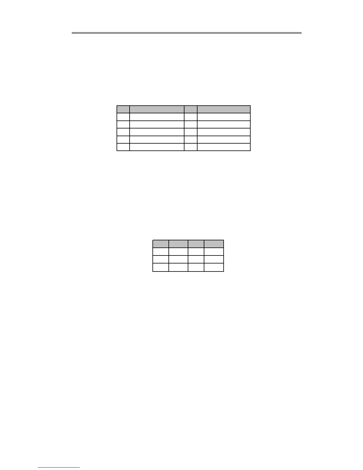
Here is a list of USB pin assignments.
1. Locate the F_USB1/2 header on the motherboard.
2. Plug the bracket cable onto the F_USB1/2 header.
3. Remove a slot cover from one of the expansion slots on the system
chassis. Install an extension bracket in the opening. Secure the extension
bracket to the chassis with a screw.
IR1: Infrared Port Header
The infrared port allows the wireless exchange of information between your
computer and similarly equipped devices such as printers, laptops, Personal
Digital Assistants (PDAs), and other computers.
1. Locate the infrared port-IR1 header on the motherboard.
2. If you are adding an infrared port, connect the ribbon cable from the port
to the SIR1 header and then secure the port to an appropriate place in
your system chassis.
Pin Signal Pin Signal
1 VERG_FP_USBPWR0 2 VERG_FP_USBPWR0
3 USB_FP_P0(-) 4 USB_FP_P1(-)
5 USB_FP_P0(+) 6 USB_FP_P1(+)
7 GROUND 8 GROUND
9 KEY 10 USB_FP_OC0
Pin Signal Pin Signal
1NC2KEY
3+5V 4GND
5 IRTX 6 IRRX
F_USB1/2: Front Panel USB Headers
The motherboard has USB ports installed on the rear edge I/O port array.
Additionally, some computer cases have USB ports at the front of the case. If
you have this kind of case, use auxiliary USB headers F_USB1/2 to connect the
front-mounted ports to the motherboard.
 Loading...