18
Installing the Motherboard
USB1~2: Front Panel USB headers
The motherboard has four USB ports installed on the rear edge I/O port array.
Additionally, there are two USB headers onboard. Use the auxiliary USB headers to
connect the front-mounted ports to the motherboard.
IR1: Infrared header (Optional)
The mainboard supports an Infrared (IR1) data port. Infrared ports allows the wire-
less exchange of information between your computer and similarly equipped devices
such as printers, laptops, Personal Digital Assistants (PDAs), and other computers.
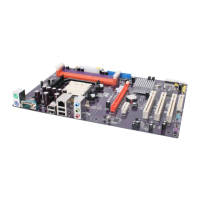
Pin Signal Name Function
1 Not Assigned Not assigned
2 Key No pin
3 +5V IR Power
4 GND Ground
5 IR_TX IrDA serial output
6 IR_RX IrDA serial input
Pin Signal Name Function
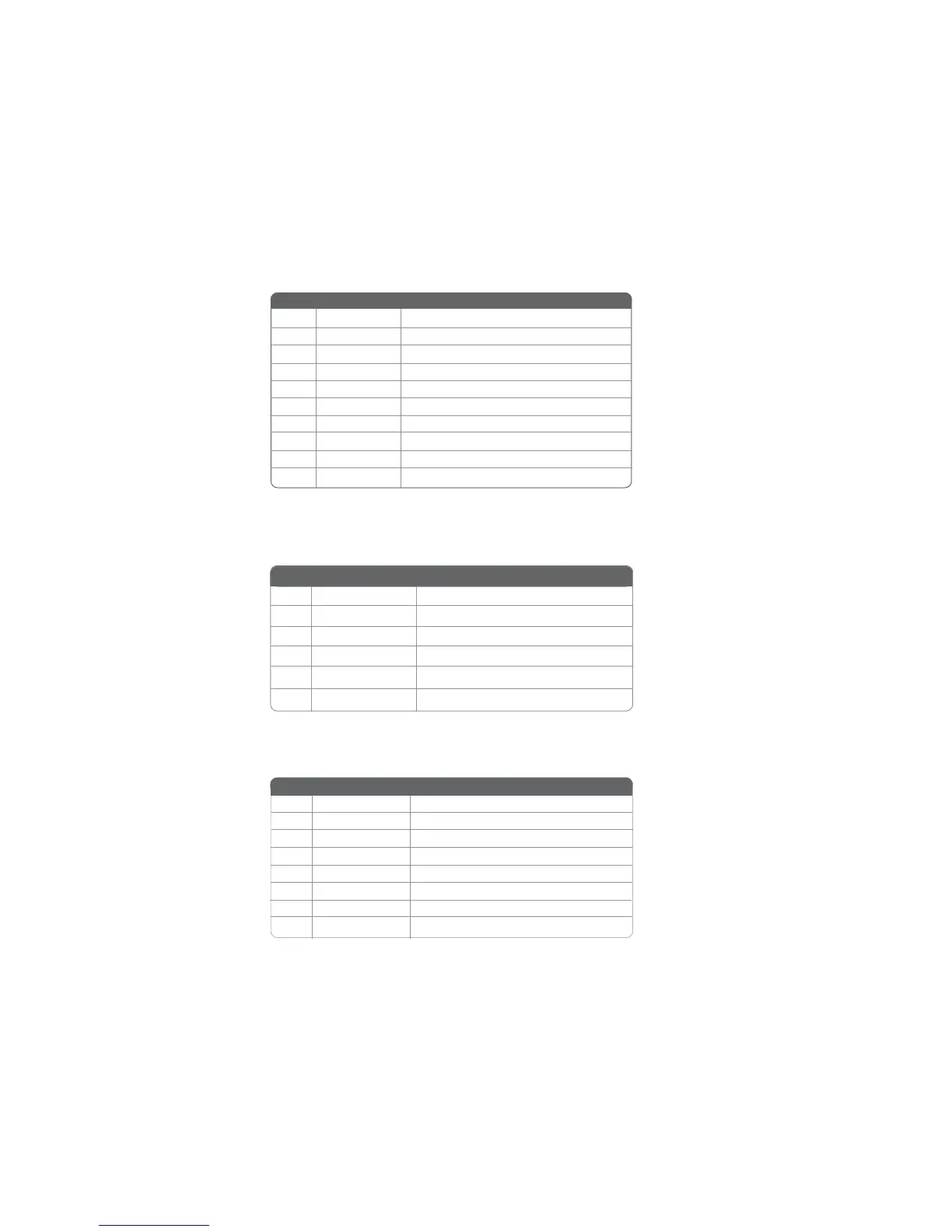
1 USBPWR Front Panel USB Power
2 USBPWR Front Panel USB Power
3 USB_FP_P0- USB Port 0 Negative Signal
4 USB_FP_P1- USB Port 1 Negative Signal
5 USB_FP_P0+ USB Port 0 Positive Signal
6 USB_FP_P1+ USB Port 1 Positive Signal
7 GND Ground
8 GND Ground
9 Key No pin
10 USB_FP_OC0 Overcurrent signal
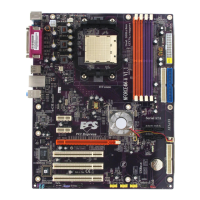
SPI_ROM1: SPI ROM Header (Optional)
This 8 Mb ROM contains the programmable BIOS program.
1 CHIP SELECT Select chip
2 VCC VCC
3 DATA OUTPUT Data output
4 HOLD Hold
5 WRITE PROTECT BIOS write protect
6 CLOCK Clock
7 CND CND
8 DATA INPUT Data input
Pin Signal Name Function