23
Installing the Motherboard
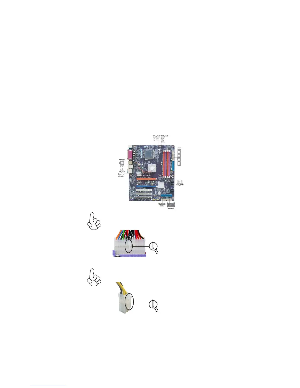
Connecting Case Components
After you have installed the motherboard into a case, you can begin connecting the
motherboard components. Refer to the following:
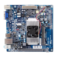
1 Connect the CPU cooling fan cable to CPU_FAN1.
2 Connect the system cooling fan connector to SYS_FAN1.
3 Connect the case fan connector to CAS_FAN1.
4 Connect the northbridge fan connector to NB_FAN1.
5 Connect the connector for graphics interface to ATX4P1.
6 Connect the case switches and indicator LEDs to the PANEL1.
7 Connect the standard power supply connector to ATX1.
8 Connect the auxiliary case power supply connector to ATX12V1.
9 Connect the case speaker cable to SPK1.
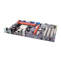
Users please note that the 24-pin power cable can be connected to the
ATX1 connector.
With ATX v2.x power supply, users
please note that when installing 24-
pin power cable, the latches of power
cable and the ATX1 match perfectly.
Connecting 24-pin power cable
24-pin power cable
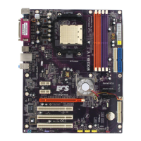
When installing 4-pin power cable, the
latches of power cable and the
ATX12V1 match perfectly.
4-pin power cable
Connecting 4-pin power cable
The ATX12V1 power connector is used to provide power to the CPU.