DIGITAL ECU TUNER 3 – User Manual
Tables
Digital Ecu Tuner 3, has 4 3D, 16x 16 tables which allow to modify / generate signals in the engine’s speed and
load functions. Additionally, every 3D table has two 2D correction tables assigned (16x1).
Interface description
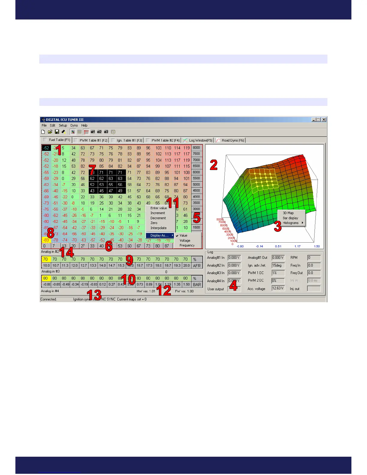
1) Table’s area is 16x16. Values in the table’s cells have different meanings for each map (and sometimes mode):
- for the Fuel Table, the values mean a change of a defined input signal (Analog In), or a change of the
frequency of the signal from the input Ignition#2 In (more on the topic can be found in the chapter about
frequency signals’ modification.).
- for the PWM1/PWM2 tables, values in the cells denote the level of impulse duty cycle (0 – 100%). In
the mode of the direct injectors steering, table values range from 0 – 200%.
- for the Ignition table, values in the cells denote the angle of the ignition retard (negative values), or
ignition advance (positive values).
2) 3D table graphics representation. To rotate the 3D graph, keep the left mouse button pressed and move it on the
3D area.
Page 10
www.ecumaster.com