DIGITAL ECU TUNER 3 – User Manual
Connector pin data
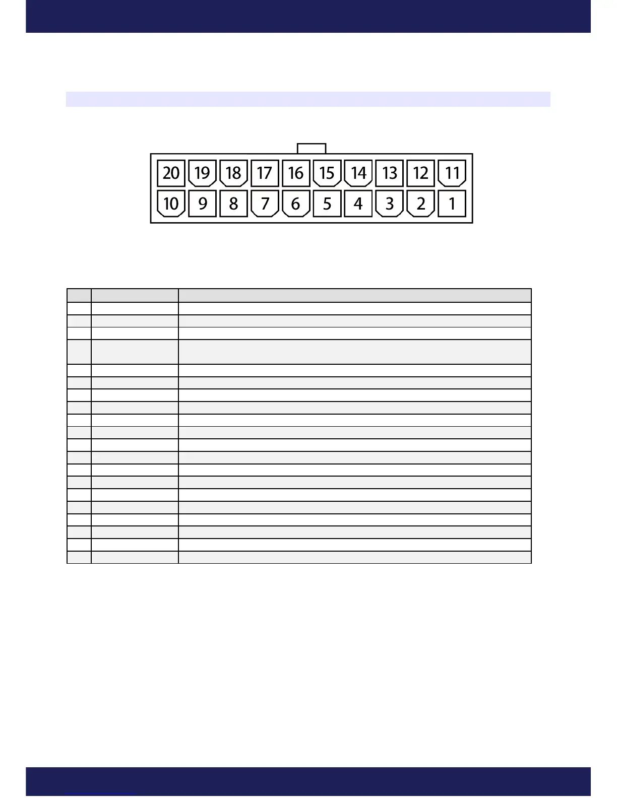
Front view of the device
Signals connector
Pin Name Description
1 +12V Power supply after the “ignition switch”. 1A fuse should be used.
2 Maps Switch Input for changing table sets.
3 Pullup Pullup resistor 2K to +12V
4 Bipolar ign. out
inverted
A complementary output of the ignition of the bipolar signal for differential
signals
5 Bipolar ign. out Ignition output for the bipolar signal.
6 Ignition out Ignition output for the unipolar signal.
7 Frequency out Frequency output
8 Pullup Pullup resistor 2K to +12V
9 Ignition in Ignition input for unipolar and bipolar signals
10 Frequency in Frequency input
11 Ground The device’s Ground
12 +5V out Output +5V for feeding of the additional sensors (for example, map sensor)
13 Analog #1 in Analog Input #1
14 Analog #2 in Analog Input #2
15 Analog #3 in Analog Input #3
16 Analog #4 in Analog Input #4
17 Analog out Analog Output
18 Power out #2 Power Output, parametric or PWM, 5A
19 Power ground Ground used for feeding of the power outputs
20 Power out #1 Power Output PWM, 5A
Page 7
www.ecumaster.com