DIGITAL ECU TUNER 3 – User Manual
For example, for Opel Astra (Astra Vauxhall ) these values are 0.28 and 2.06 m2. For Audi A3 0.31 and 2.13 m2,
respectively. There is also an option to correct the graph concerning the car’s rolling resistance. It is important
though to have data about the loses on a given gear in the revolutions function ( for example, a graph from the
roller dynamometer with the loss put on it). Next, these data should be written in the Trans and tires looses table.
To activate the correction concerning the resistance on the graph, select the Enable trans. losses corr. checkbox.
It is also possible to set filtering of the analog inputs signals, which will also be placed on the power graph. In the
Filters section, values are describing filtering power. The higher the value is, the more smooth the analog inputs
graphs are. The defined parameters can be saved by using the Save option and read in again by using the Load
option. To generate the dyno graph, data should be collected in the first place. To do this, press the Start Dyno
button in the log bookmark. After finishing measuring the drive, press the End Dyno. Button. It is also possible to
generate the power graphs from a normally collected data log. However, in the “Dyno” mode, the software is able
to collect more precise data. Next, an area, from which the graph will be generated, should be marked. It is
important to make sure that the marked graph is the monotonic function. To mark the log area, click the right mouse
button in the chosen area and choose an option: either Dyno Start Marker or Dyno End Marker. The marked area
will be highlighted in blue. Next, choose the Make Dyno Graph. Now we can choose tab Dyno (F6 button) to see
the graph.
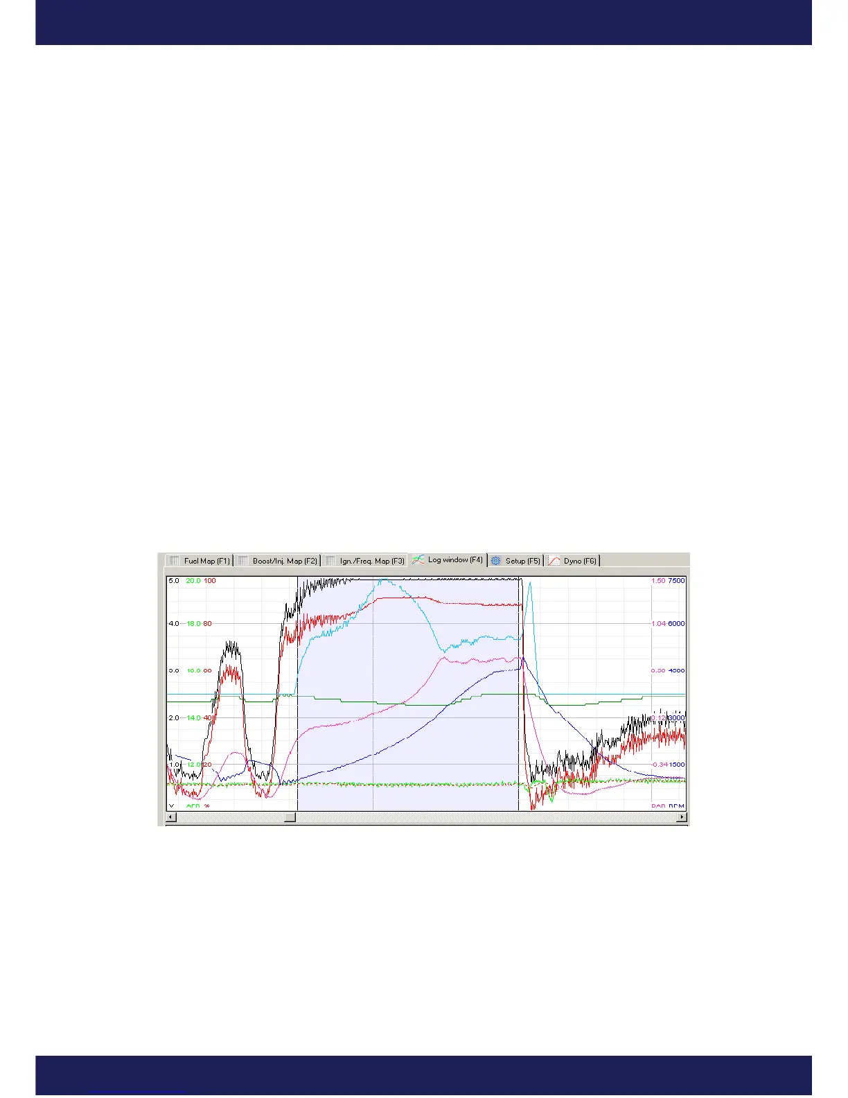
A correctly marked area from which a power graph will be generated is presented below.
If the input data will be “disturbed” (noisy graph of the rotation speed), the parameter Filter Power should be
increased.
Page 40
www.ecumaster.com