– 23 –
FIGURES
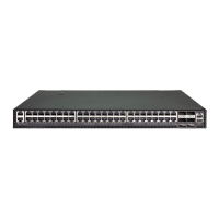
Figure 1: Front Panel 25
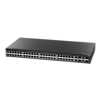
Figure 2: Rear Panel 26
Figure 3: Port and System Status LEDs 28
Figure 4: Power Supply Socket 29
Figure 5: Network Aggregation Plan 30
Figure 6: Remote Connections with Fiber Cable 31
Figure 7: RJ-45 Plug 34
Figure 8: Attaching the Brackets 37
Figure 9: Installing the Switch in a Rack 37
Figure 10: Attaching the Adhesive Feet 38
Figure 11: Inserting an SFP Transceiver into a Slot 39
Figure 12: Power Sockets 40
Figure 13: Serial Port (DB-9 DTE) Pin-Out 41
Figure 14: Making Twisted-Pair Connections 44
Figure 15: Network Wiring Connections 45
Figure 16: Making Fiber Port Connections 47
Figure 17: RJ-45 Connector Pin Numbers 53
Figure 18: Straight-through Wiring 55
Figure 19: Crossover Wiring 55
 Loading...