Chapter 1
| Switch Description
Overview
– 12 –
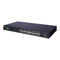
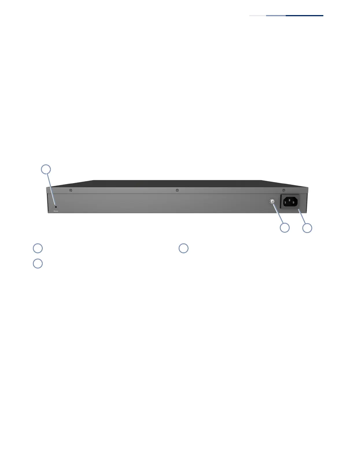
Reset Button
Pressing the Reset button on the rear panel causes the switch to perform a hard
reset. For more information, see “How to Reset the Switch” on page 43.
System LEDs
For information on system status LED indicators, see “Understanding the System
Status LEDs” on page 40.
Port LEDs
For information on port status LED indicators, see “Understanding the Port Status
LEDs” on page 29.
Figure 2: Rear Panel
Console Port
The RJ-45 connector on the front panel far right side that is labeled “Console”
provides an out-of-band serial connection to a terminal or a PC running terminal
emulation software. The port can be used for performing switch monitoring and
configuration. For more information, see “How to Connect to the Console Port” on
page 41.
Cooling Fans and Vents
It is recommended that the switch is installed in a properly cooled and ventilated
environment. For more information, see “Switch Cooling Requirements” on
page 23.
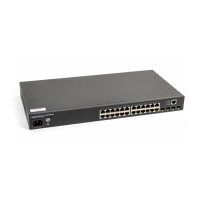
AC Power Socket
The switch requires a 100-240VAC, 50-60Hz AC power source. For more information
on the switch power input, how to connect it, and how to power-on the switch, see
“How to Connect to AC Power” on page 26.
Reset Button AC Power Socket
Ground Point
 Loading...