Chapter 1
| Switch Description
Overview
– 11 –
Key Hardware
Components
The switch consist of serveral key hardware components. This manual describes
each specific component, or related components, together with their installation
requirements and procedures in each chapter. To understand each component in
detail, refer to the relevant section.
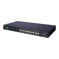
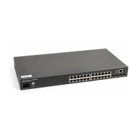
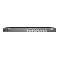
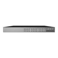
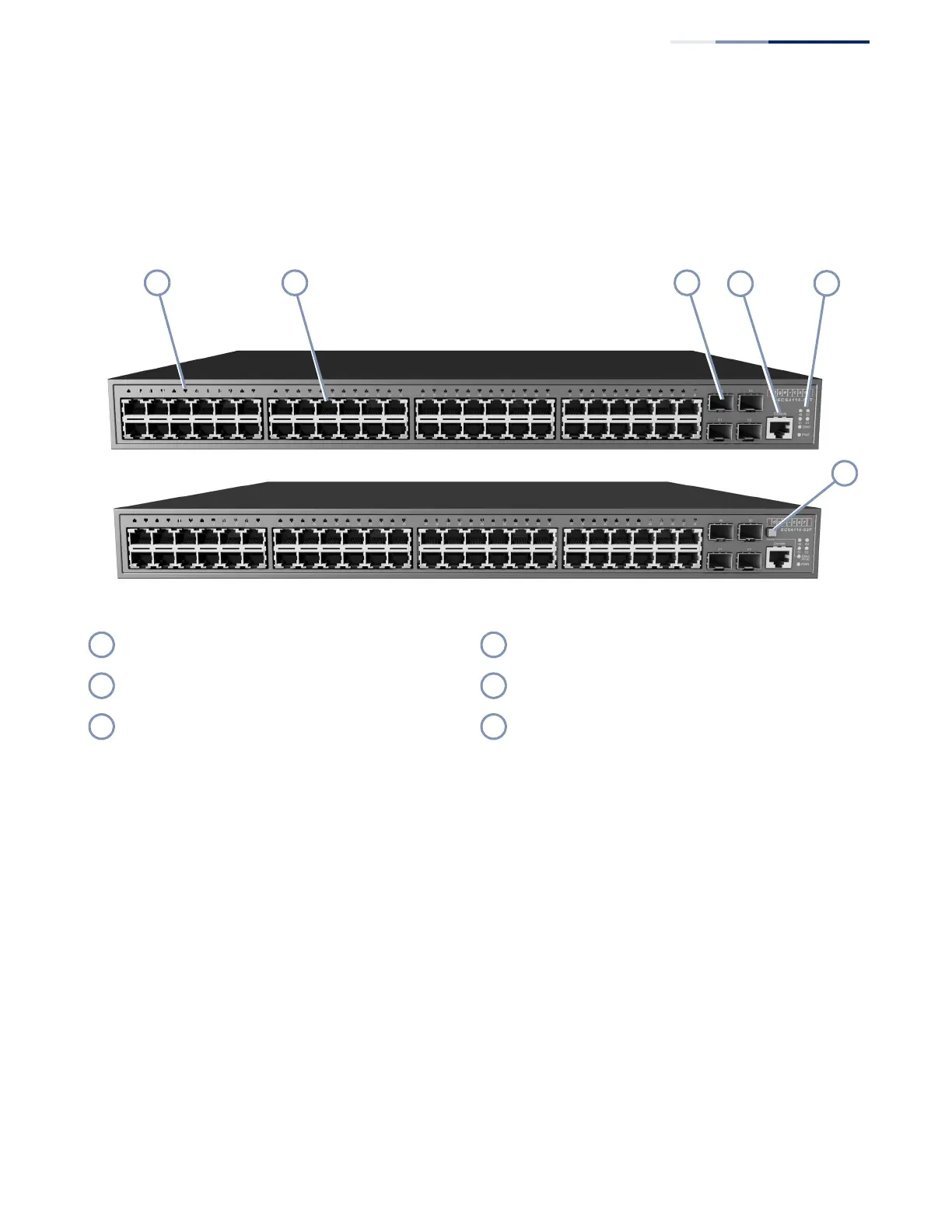
Figure 1: Front Panel ECS4110-52T (upper) and ECS4110-52P (lower)
10/100/1000BASE-T RJ-45 Ports
The switch contains 48 10/100/1000BASE-T RJ-45 ports that support 10/100/
1000BASE-T copper links to other devices. For more information, see “How to
Connect to Twisted-Pair Copper Ports” on page 32.
Gigabit SFP Slots
The switch contains four Small Form Factor Pluggable (SFP) transceiver slots that
operate up to Gigabit full duplex. For more information, see “How to Connect to
SFP Fiber Optic Ports” on page 36.
Mode Button (ECS4110-52P only)
Pressing the Mode button on the front panel will change the Diag LED to display
PoE status. For more information, see “Understanding the System Status LEDs” on
page 40.
Port LEDs RJ-45 Console Port
1000BASE-T RJ-45 Ports System LEDs
Gigabit SFP Slots LED Mode Button (ECS4110-52P only)
 Loading...