– 8 –
Figures
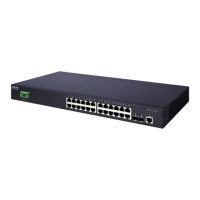
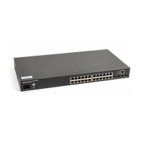
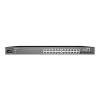
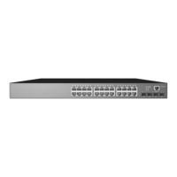
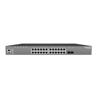
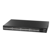
Figure 1: Front Panel ECS4110-52T (upper) and ECS4110-52P (lower) 11
Figure 2: Rear Panel 12
Figure 3: Installing the Switch in a Rack 15
Figure 4: Connecting AC Power 16
Figure 5: System LEDs 17
Figure 6: Console Port 17
Figure 7: Making a Connection to a SFP Port 18
Figure 8: Attaching the Brackets 21
Figure 9: Installing the Switch in a Rack 21
Figure 10: Attaching the Adhesive Feet 22
Figure 11: Switch Cooling 23
Figure 12: AC Power Supply Socket 24
Figure 13: Grounding Terminal 25
Figure 14: AC Power Cord and Power Socket 26
Figure 15: Port Status LEDs 29
Figure 16: Inserting an SFP Transceiver into a Slot 31
Figure 17: RJ-45 Connector 33
Figure 18: Making Twisted-Pair Connections 35
Figure 19: Making a Connection to a SFP Port 37
Figure 20: System Status LEDs 40
Figure 21: Console Port 41
Figure 22: Console Port Connection 42
Figure 23: Reset Button 43
 Loading...