Chapter 5
| Port Connections
How to Connect to Twisted-Pair Copper Ports
– 36 –
1000BASE-T Cable Requirements
All Category 5 UTP cables that are used for 100BASE-TX connections should also
work for 1000BASE-T, providing that all four wire pairs are connected. However, it is
recommended that for all critical connections, or any new cable installations,
Category 5e (enhanced Category 5) or Category 6 cable should be used. The
Category 5e and 6 specifications include test parameters that are only
recommendations for Category 5. Therefore, the first step in preparing existing
Category 5 cabling for running 1000BASE-T is a simple test of the cable installation
to be sure that it complies with the IEEE 802.3-2008 standards.
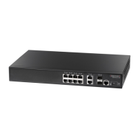
Power-over-Ethernet The ECS4210-12P switch supports both IEEE 802.3af and IEEE 802.3at-2009 PoE
standards that enable DC power to be supplied from eight of the switch’s RJ-45
copper ports (ports 1-8) to connected devices by utilizing certain pairs of the
connecting Ethernet cable.
The total PoE power delivered by all ports cannot exceed the 150 W power budget.
This means that up to 4 ports can supply a maximum 30 W of power simultaneously
to connected devices, or all 8 ports can supply up to 16.7 W simultaneously.
Any PoE-compliant device attached to a port can directly draw power from the
switch over the Ethernet cable without requiring its own separate power source.
This capability gives network administrators centralized power control for devices
such as IP phones and wireless access points, which translates into greater network
availability.
For each attached PoE-compliant device, the switch automatically senses the load
and dynamically supplies the required power. The switch delivers power to a device
using the wire pairs in UTP or STP cable.
3 Bi-directional Pair B Plus (BI_DB+)
GND (Positive V
port)
Bi-directional Pair A Plus (BI_DA+)
-52V power (Negative Vport)
4 Bi-directional Pair C Plus (BI_DC+)
-52V power (Negative V
port)
Bi-directional Pair D Plus (BI_DD+)
GND (Positive Vport)
5 Bi-directional Pair C Minus (BI_DC-)
-52V power (Negative V
port)
Bi-directional Pair D Minus (BI_DD-)
GND (Positive Vport)
6 Bi-directional Pair B Minus (BI_DB-)
GND (Positive Vport)
Bi-directional Pair A Minus (BI_DA-)
-52V power (Negative Vport)
7 Bi-directional Pair D Plus (BI_DD+)
GND (Positive Vport)
Bi-directional Pair C Plus (BI_DC+)
-52V power (Negative Vport)
8 Bi-directional Pair D Minus (BI_DD-)
GND (Positive V
port)
Bi-directional Pair C Minus (BI_DC-)
-52V power (Negative Vport)
Table 6: 1000BASE-T MDI and MDI-X Port Pinouts (Continued)
Pin MDI Signal Name MDI-X Signal Name
 Loading...