– 21 –
FIGURES
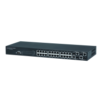
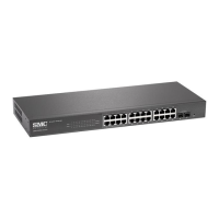
Figure 1: Front Panel 22
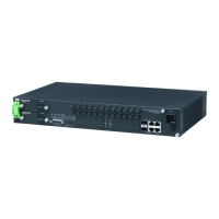
Figure 2: Rear Panel 22
Figure 3: Port and System LEDs 24
Figure 4: Power Supply Inlet 26
Figure 5: Reset Button 26
Figure 6: Collapsed Backbone 29
Figure 7: Network Aggregation Plan 30
Figure 8: Remote Connections with Fiber Cable 31
Figure 9: Making VLAN Connections 32
Figure 10: RJ-45 Connections 35
Figure 11: Attaching the Brackets 38
Figure 12: Installing the Switch in a Rack 38
Figure 13: Attaching the Adhesive Feet 39
Figure 14: Power Inlet 40
Figure 15: Installing an Optional SFP Transceiver into a Slot 41
Figure 16: Making Twisted-Pair Connections 43
Figure 17: Network Wiring Connections 44
Figure 18: Making Fiber Port Connections 46
 Loading...