C
HAPTER
1
| Introduction
Overview
– 24 –
The following table shows a list of transceiver types that have been tested with
the switch. For an updated list of vendors supplying these transceivers, contact
your local dealer. For information on the recommended standards for fiber optic
cabling, see "Fiber Optic SFP Devices" on page 45.
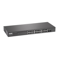
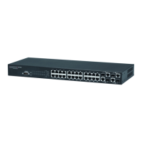
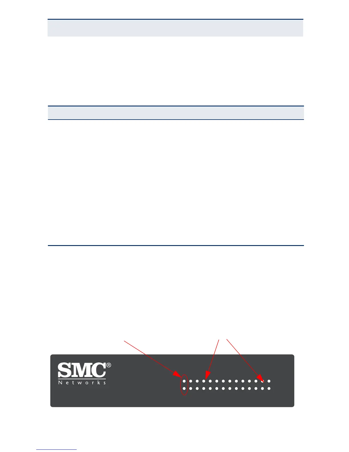
PORT AND SYSTEM LEDS
The switch includes a display panel for key system and port indications that
simplify installation and network troubleshooting. The LEDs, which are located
on the front panel for easy viewing, are shown below and described in the
following tables.
Figure 3: Port and System LEDs
Table 1: Supported SFP Transceivers
Media Standard Fiber Diameter (microns) Wavelength (nm)
Maximum Distance
*
* Maximum distance may vary for different SFP vendors.
1000BASE-SX 50/125 850 700 m
62.5/125 850 400 m
1000BASE-LX 50/125 1300 550 m
62.5/125 1300 550 m
9/125 1300 10 km
1000BASE-LH 9/125 1310 35 km
1550 80 km
100BASE-FX 50/125 or 62.5/125 1300 2 km
9/125 1300 20 km
1000BASE-T 100 m
2 4 6 8 10 12 14 16 18 20 22 24 26
1 3 5 7 9 1113151719212325
LINK ACT/
LINK ACT/
SMCGS26C
EZ Switch 10/100/1000
SMCGS26C-Smart
DIAG
PWR