C
HAPTER
1
| Introduction
Overview
– 25 –
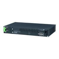
POWER SUPPLY INLET
There is one power inlet on the rear panel of the switch. The standard power
inlet is for the AC power cord.
Table 2: Port Status LEDs
LED Condition Status
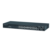
RJ-45 Gigabit Ethernet Ports (Ports 1-24)
LINK/ACT On/Flashing
Amber
Port has established a valid 10/100 Mbps network
connection. Flashing indicates activity.
On/Flashing
Green
Port has established a valid 1000 Mbps network
connection. Flashing indicates activity.
Off There is no valid link on the port.
SFP Gigabit Ethernet Ports (Ports 25-26)
(LINK/ACT) On/Flashing
Amber
Port has established a valid 100 Mbps network
connection. Flashing indicates activity.
On/Flashing
Green
Port has established a valid 1000 Mbps network
connection. Flashing indicates activity.
Off There is no valid link on the port.
Table 3: System Status LEDs
LED Condition Status
PWR On Green The unit’s internal power supply is operating normally.
Off The unit has no power connected.
DIAG On Green The system diagnostic test has completed successfully.
On Amber Internal error is detected when sysetem is booting.
Off The system diagnostic has completed.
 Loading...