TABLE OF CONTENTS INTRODUCTION INSTALLATION OPERATING INSTRUCTIONS APPENDIX
1. Locate Fuel Pressure Sensor connector. (Figure 6)
2. Remove vehicle Fuel Pressure Sensor connector and connect the Edge Har-
ness Fuel pressure sensor connector “T” in between the vehicle harness and the
sensor itself. (Similar to Figure 7 on previous page)
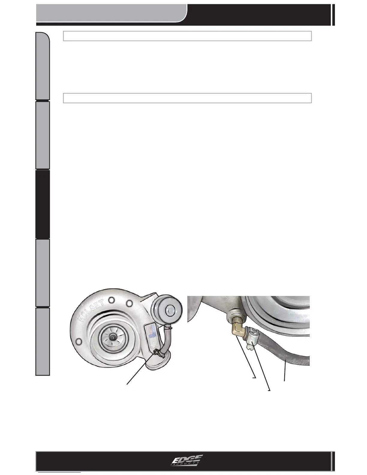
Figure 9 - Installed Boost Elbow
Edge Supplied Elbow
Hose Clamp
Hose
Figure 8 - Turbo View
OEM brass fi tting
BOOST ELBOW INSTALLATION (OPTIONAL)
2. Remove the hose and set it aside.
3. Using the pliers, remove the crimp style clamp from the hose on the brass
fi tting located on the now exposed lower front side of the turbocharger.
4. Remove the hose from the brass fi tting and dispose of the crimp style clamp.
5. Using the 7/16” wrench, unscrew the stock brass fi tting out of the turbocharg-
er housing.
7. Slip the supplied hose clamp onto the stock hose, install the stock hose
onto the supplied brass fi tting and tighten the hose clamp with the ¼” socket.
8. Reinstall the stock air hose onto the air fi lter housing and turbocharger inlet.
9. Using the 5/16” socket, tighten both clamps securely.
1. Using the 5/16” socket, loosen the two clamps securing the air induction hose
to the air fi lter housing and the turbo inlet. (Figure 8)
6. Using the 7/16” wrench, install the supplied brass fi tting. Tighten while being
careful not to over-tighten. (Figure 9)
CONNECTING TO FUEL PRESSURE SENSOR
NOTE: YOUR JUICE MODULE INSTALLATION IS NOT COMPLETE. RE-
FER TO THE “EGT PROBE INSTALLATION” SECTION TO CONTINUE.