EGT PROBE INSTALLATION
WARNING When installing the EGT Thermocouple, wear eye protec-
tion and protective clothing to protect from getting metal chips in your eyes.
Also, since exhaust manifolds can be very hot, allow the engine to cool before
drilling. When working under the vehicle, make sure the park brake is set.
- Drill
- 1/8” drill bit or similar size (for pilot hole)
- 21/64” (best size) or 5/16” drill bit
- 9/16” wrench or socket
- 5/8” open end wrench
- 1/8”-27 NPT Thread Tap
- Phillips screwdriver
- 5/16” or 8mm wrench
CAUTION: One effective way to avoid metal fragment contamination in your
engine manifold is to apply grease in the tip of the drill bit and threads of your
tap tool when drilling/tapping the hole in your manifold. Reduce pressure
on the drill when the drill breaks through the manifold wall to reduce risk of
pushing metal chips into the manifold.
1. Obtain a 1/8”-27 NPT Thread Tap available from your hardware store.
2. Drill a 21/64” (5/16” optional) hole through the manifold wall.
3. Use the pipe tap to cut the threads in accordance to the pipe tap manufac-
turer’s instructions and recommendations.
TAPPING AND PROBE INSTALLATION
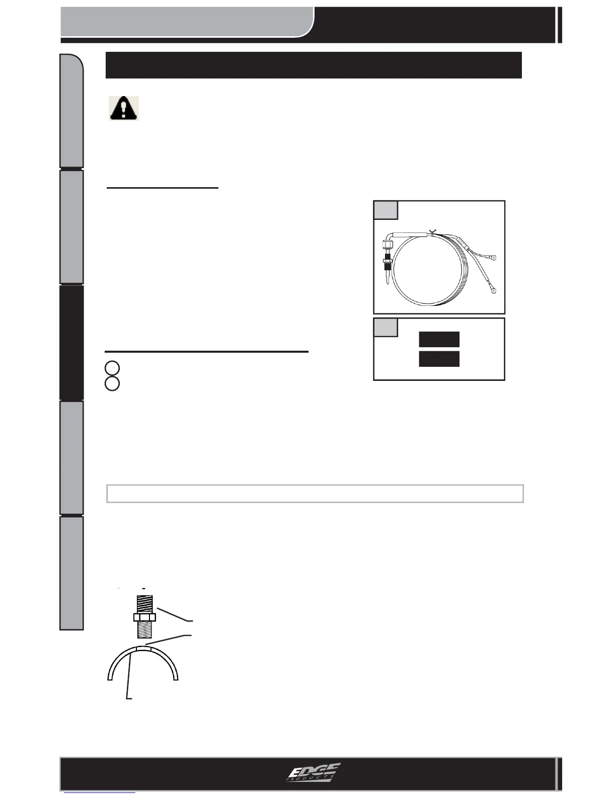
4. Remove the fi tting from the Thermo-
couple and install by tightening the tapered
thread end into the manifold. (Figure 1)
5. Tighten the fi tting so that it is securely
seated.
Supplied Items Qty
Required Tools
1 EGT Probe..................................(1)
2 Shrink Tube................................(2)
2
1
NOTE: Ideally the tip of the fi tting would
be less than or fl ush with the inside of the
exhaust fl ow path. (Figure 2)
Exhaust Manifold Wall
Figure 1 - Fitting Installation
Fitting
Exhaust M
Tapped Hole


 To Next Page