4-12 SECTION 4: Maintenance and Troubleshooting
3200-XS Sub-Bottom Profiling System User’s Manual Doc. No. 990-0000026-1000, Rev. 2.3
4.6 Wiring and Connector Pinout Drawings
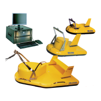
Listed in Table 4-4 and included in the following pages are the 3200-XS Sub-Bottom
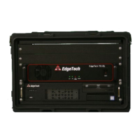
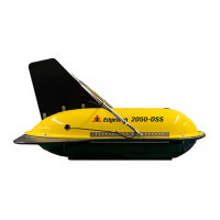
Profiling System wiring and connector pinout drawings for the Deck Unit and the SB-424,
SB-216S and SB-512i Tow Vehicles. For the Deck Unit a wiring harness diagram and
connector pinout information are provided. For each of the tow vehicles, spider mold and
tow vehicle wiring diagrams are provided. The spider mold wiring diagrams also include
connector pinout information. In addition, a wiring diagram with connector pinout
information for the 75-Meter Kevlar Reinforced Tow Cable is included.
Table 4-4:
List of Wiring and Connector Pinout Drawings
DRAWING NUMBER TITLE
B962374 Wiring Harness, Deck Unit
503-0000008-1000 Wiring Diagram, Spider Box, SB-424 Tow Vehicle
A980966 Wiring Diagram, SB-424 Tow Vehicle
503-0000006-1000 Wiring Diagram, Spider Box, SB-216S Tow Vehicle
A980965 Wiring Diagram, SB-216S Tow Vehicle
503-0000013-1000 Wiring Diagram, Spider Box, SB-512i Tow Vehicle
A980964 Wiring Diagram, SB-512i Tow Vehicle
505-0000010-1000 Wiring Diagram, 75-Meter Kevlar Reinforced Tow Cable