xiv
3200-XS Sub-Bottom Profiling System User’s Manual Doc. No. 990-0000026-1000, Rev. 2.3
List of Figures
Figure 1-1: Deck Unit . . . . . . . . . . . . . . . . . . . . . . . . . . . . . . . . . . . . . . . . . . . . . . . . . . . . . . . 1-5
Figure 1-2: Tiger and Mother Boards inside 3200-XS Topside Processor . . . . . . . . . . . . . . . 1-6
Figure 1-3: 75-Meter Kevlar Reinforced Tow Cable . . . . . . . . . . . . . . . . . . . . . . . . . . . . . . . . 1-7
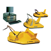
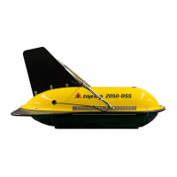
Figure 1-4: SB-424, SB-216S and SB-512i Tow Vehicles . . . . . . . . . . . . . . . . . . . . . . . . . . . 1-8
Figure 1-5: Tiger Board Set . . . . . . . . . . . . . . . . . . . . . . . . . . . . . . . . . . . . . . . . . . . . . . . . . 1-10
Figure 3-1: Deck Unit Back Side . . . . . . . . . . . . . . . . . . . . . . . . . . . . . . . . . . . . . . . . . . . . . . 3-4
Figure 3-2: Deck Unit Front Side . . . . . . . . . . . . . . . . . . . . . . . . . . . . . . . . . . . . . . . . . . . . . . 3-5
Figure 3-3: Behind 3200-XS Topside Processor Access Panel . . . . . . . . . . . . . . . . . . . . . . . 3-6
Figure 3-4: A 75-Meter Kevlar Reinforced Tow Cable Shown Connected and Attached
to an SB-216S Tow Vehicle . . . . . . . . . . . . . . . . . . . . . . . . . . . . . . . . . . . . . . . . . 3-9
Figure 3-5: Recommended Method for Dressing and Strain Relieving the Tow Cable . . . . . 3-9
Figure 3-6: The DISCOVER 3200SB Main Window . . . . . . . . . . . . . . . . . . . . . . . . . . . . . . . 3-12
Figure 3-7: The Options Dialog Box, Sonar Control Tab . . . . . . . . . . . . . . . . . . . . . . . . . . . 3-12
Figure 4-1: Retaining Ring and Locking Sleeve . . . . . . . . . . . . . . . . . . . . . . . . . . . . . . . . . . . 4-3
Figure 4-2: Retaining Ring and Locking Sleeve Removed . . . . . . . . . . . . . . . . . . . . . . . . . . . 4-3
Figure 4-3: SB-424, SB-216S and SB-512i Tow Vehicle Transducers, Hydrophones,
Transformers, Inductors, Spider Boxes, Spider Arrays, And Preamplifiers . . . . . 4-4
Figure 4-4: Removing the 7/16-Inch Bolts Securing the Teardrop Cover to the
Tow Vehicle . . . . . . . . . . . . . . . . . . . . . . . . . . . . . . . . . . . . . . . . . . . . . . . . . . . . . 4-5
Figure 4-5: Removing the Teardrop Cover . . . . . . . . . . . . . . . . . . . . . . . . . . . . . . . . . . . . . . . 4-5
Figure 4-6: Teardrop Cover Removed . . . . . . . . . . . . . . . . . . . . . . . . . . . . . . . . . . . . . . . . . . 4-6
Figure 4-7: Removing 7/16 and 1/2-Inch Bolts and Nuts Securing the Top Cover of
the Tow Vehicle Body . . . . . . . . . . . . . . . . . . . . . . . . . . . . . . . . . . . . . . . . . . . . . 4-6
Figure 4-8: SEA CABLE Connector—Female, Face View . . . . . . . . . . . . . . . . . . . . . . . . . . 4-11
Figure 4-9: Tow Vehicle Tow Cable Connector—Male, Face View . . . . . . . . . . . . . . . . . . . 4-11