2-1
• Figure 2-13 Location of the CT to VT links
Figure 2-14 shows the screw used at this link.
• Figure 2-14 The screw used to form the CT-VT link
It is important to leave the other screws in place, as they are part of the connection of the
voltage terminals to the meter.
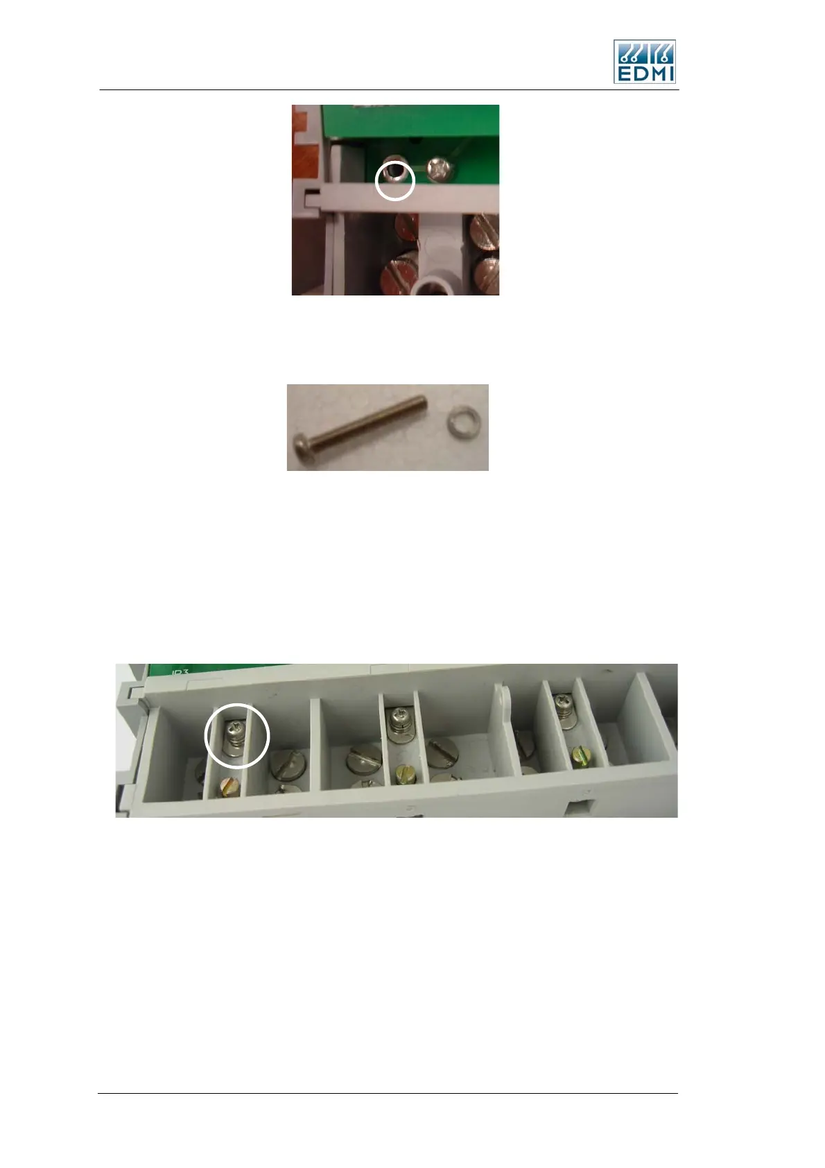
In the new design, the links are located in the terminal block area near the current
screws. Figure 2-15 shows the location of the link screws, with the phase A link
highlighted. There is no link for the neutral – that link is made internally in a similar
fashion to the old style terminal block, and should not need to be removed.
• Figure 2-15 Location of the CT to VT links
To break the link the screws should be removed, leaving just the metal tab (Figure
2-16).
2-12 EDMI Atlas Hardware Reference Manual

 Loading...