D397-21-880 Issue G
Page 14 © Edwards Limited 2009. All rights reserved.
Edwards and the Edwards logo are trademarks of Edwards Limited.
Installation
Two types of relay box are available as options from Edwards with either 3 or 6 relay outputs.
The relay box has built in relays that can switch external loads and provides a connector to interface to an external
system. Refer to the relay box instructions for further information on using the setpoint outputs.
To drive a relay without a relay box, connect the coil of a suitable 24 V d.c. relay between 'Setpoint Output' (negative)
and 'Power Supply Positive' (positive).
Alarm:
Alarm can be used to interface to external logic or can be used to drive a relay. This output is normally active
and will become inactive in the event of an alarm condition.
To drive a relay, connect the coil of a suitable 24 V d.c. relay between 'Alarm Output' (negative) and 'Power Supply
Positive' (positive).
Note: Total current drawn from 24 V pin on logic connector should be 208 mA maximum.
3.3.5 Connecting the serial interface
The TIC has two serial communications protocols built in, RS232 and RS485. RS232 is the simplest interface and can
be used to allow a host PC to control the TIC. RS485 allows a host PC to control a small network of TICs.
3.3.5.1 Connecting RS232
The TIC is fitted with a 9-way 'D' type socket on the rear panel, refer to Figure 9, item 3. The interface uses two lines
for data transfers and an additional line as a signal common. Hardware handshaking is not implemented.
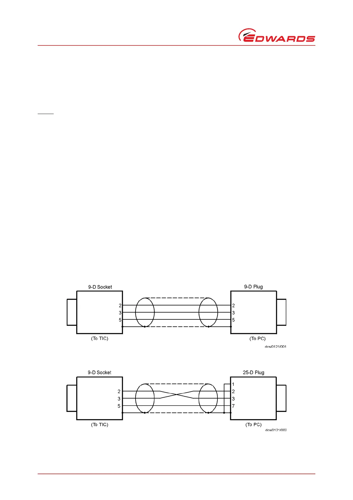
If connecting to an IBM compatible PC fitted with a 9-way 'D' type socket then a 'straight through' male-female 9-way
extension cable can be used to connect the TIC to the computer as shown in Figure 10. Connection to an IBM PC fitted
with a 25-way serial connector should be made as shown in Figure 11.
Use shielded cable for the interface to reduce interference problems and limit the length of the RS232 link to less
than 10 metres. For longer links, either install line drivers or use RS485.
Figure 10 - IBM PC RS232 interface - 9-way
Figure 11 - IBM PC RS232 interface - 25-way
 Loading...