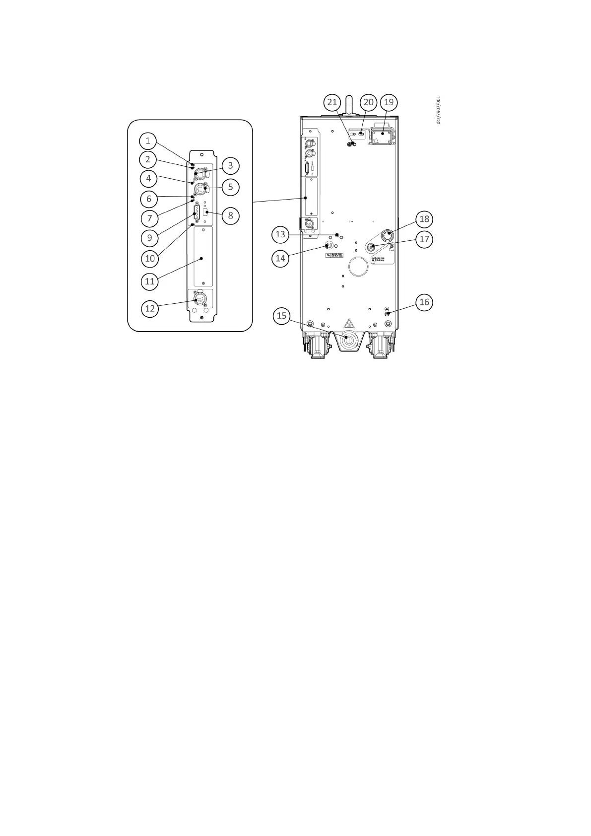
Figure 2 Controls/connectors on the rear of the system
1. Ethernet Local Area Network (LAN) LED
(gr
een)
2. Ethernet link LED (yellow)
3. Ethernet connecon
4. Power LED (green) 5. System interface connecon
6. Warning LED (yellow) 7. Running and alarm LEDs (2 colours,
either green or red)
8. USB connecon 9. Accessory interface connecon
10. MicroTIM in control LED (green) 11. Micro TIM connecon (if installed)
12. EMS interface 13. N
2
purge adjuster
14. Nitrogen purge connecon 15. Exhaus
t gas outlet
16. RF earth (ground) stud 17. Cooling water supply connecon
18. Cooling w
ater supply return 19. Electrical supply connecon
20. Electrical connector locking mechanism 21. Protecve earth (gr
ound) stud
2.2 Applicaons
The iXM pumping s
ystem is intended for use on applicaons as shown in Figure:
Applicaons.
The pump warranty will be invalid if the system is used on any other applicaon. Contact
your supplier if you are in doubt, for advice on the suitability of the system for any
parcular applicaon.
10/2020 - ©Edwards Limited
Page 11M56635880_D
M56635880_D - General descripon