EasyManua.ls Logo

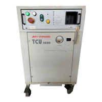
Edwards TCU 40/80

Edwards TCU 40/80
76 pages
To Next Page IconTo Next Page
To Previous Page IconTo Previous Page
Loading...
Table
5
-
Front
panel
LED
indicators
LED
name
FACILITY
POWER
FACILITY
WATER
CIRCUIT
BREAKERS
COMPRESSOR
COOLANT
TEMPERATURE
COOLANT
FLOW
COOLANT
NORMAL
LEVEL
COOLANT
LOW
LEVEL
REMOTE
RTD
Condition
Green
Red
Green
Red
Green
Red
Green
Red
Green
Red
Green
Red
Green
Amber
Off
Amber
Red
Off
Green
Description
Power
phases
are
normal.
Power
phases
are
reversed
or
low
line
voltage.
Water
pressure
and
flow
are
normal.
Water
pressure
or
flow
are
not
adequate.
(See
Specifications
on page
14.
Rear
panel
circuit
breakers
2, 3,
and
4
are
on.
One
or
more
of
these
breakers
is
tripped
or
off.
Compressor
is
operating
normally.
Compressor
has
stopped
operating.
Coolant
reservoir
temperature
is
normal.
Coolant
temperature
is
above
the
operating
range.
Coolant
flow
is
normal.
Coolant
flow
is
not
adequate.
Coolant
level
is
normal.
Coolant
level
is
over
filled.
Coolant
level
is
normal
Coolant
level
is
low.
Coolant
level
is
very
low.
Remote
RTD
not
connected.
Remote
RTD
temperature
probe
is
in
use.
Table
6
-
Temperature
controller
Controls
and
indicators
Process
Value
(PV)
Setpoint
Value
(SP)
Pushbuttons
Remote
Mode
LED
(Aux)
Description
The
present
temperature
of
the
coolant,
as
indicated
by
the
internal
RTD
or
the
remote
RTD.
The
TCU
40/80
regulates
to this
temperature,
as
set
by
the
operator.
Used
to
program
the
controller.
Indicates
mode
of
operation:
Off
indicates
local
operation.
On
indicates
remote
operation.
12
TCU
40/80
Temperature
Control
Unit

Related product manuals