EasyManua.ls Logo

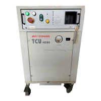
Edwards TCU 40/80

Edwards TCU 40/80
76 pages
To Next Page IconTo Next Page
To Previous Page IconTo Previous Page
Loading...
ILLUSTRATIONS
Figure
Title
Page
Figure
1-
Refrigeration
and
coolant
components
6
Figure
2
-
Refrigeration
and
coolant
components
7
Figure
3-
Refrigeration
and
coolant
circuits
9
Figure
4
-
Front panel
11
Figure
5
-
Electrical
rear
panel
13
Figure
6
-
TCU
dimensions
15
Figure
7-
Stacked
TCU
40/80
systems
17
Figure
8-System
rear
view
18
Figure
9
Water
connections
J9
Figure
10
-
Temperature
controller
21
Figure
11
-
Lamp
replacement
29
Figure
12
-
Solenoid
coil
replacement
31
Figure
13
-Electrical
drawer
51
Figure
14-Electrical
drawer
schematic
54
Figure
15
-
Remote
interface
56
Table
Title
Page
Table
1
-
Safety
features
4
Table2
-Frontpanel
Indicators
5
Table
3
-
Refrigeration
and
coolant
components
8
Table
4
-
Front
panel
controls
11
Table
5
-
Front
panel
LED
indicators
12
Table
6
-
Temperature
controller
12
Table
7
-
Description
of
rear
panel
components
and
indicators
13
Table
8
-
Front panel
power
up
indicator
conditions
20
Table
9
-
Electrical
hazards
classifications
25
Table
10
-
Preventive
maintenance
schedule
27
Table
11-
Faults
identified
by
front
panel
lamps
42
Table
12
-
Faults
indicated
by
the
front
panel
LED
indicators
44
Table
13
-Faults
identified
by
rear
panel
indicators
48
Table
14
-
Miscellaneous
fault
conditions
49
Table
15
-Accessories
52
Table
16
Spare
parts
53
TCU
40/80
Temperature
Control
Unit
Hi

Related product manuals