EasyManua.ls Logo

Edwards TCU 40/80 - Page 26

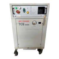
Edwards TCU 40/80
76 pages
To Next Page IconTo Next Page
To Previous Page IconTo Previous Page
Loading...
6
OPERATION
6.1
Preparation
Verify
that
water
and
coolant
connections
are
made
at
both
ends,
that
the
drain
valve
is
closed
and
the
coolant
supply
and
return
valves
are
open.
Connect
the
remote
interfaces
if
required.
1.
To
use
an
external
RTD
probe,
attach
it
to
connector
J72J3.
Refer
to
Figure
15
on
page
56.
Verify
that
the
plug
J72J2
is
installed.
2.
Press
the
EMERGENCY
OFF
button
on
the
front
panel.
3.
Plug
the
TCU
40/80
power
cord
into
a
fused,
switchable,
30
amp,
3-phase,
208
VAC
outlet.
4.
Ensure
that
all
circuit
breakers
on
the
rear
panel
are
in
the
ON
position.
CB7
and
CB8
are
non-
switchable
circuit
breakers
and
will
trip
when
there
is
a
problem.
They
cannot
be
turned
on
or
off,
but
they
are
re-settablc.
6.2
Powering
up
the
TCU
40/80
1.
Verify
that
the
POWER
ON
lamp
on
the
front
panel
is
illuminated.
2.
Release
the
EMERGENCY
OFF
button.
If
the
Facility
Power
LED
illuminates,
the
line
voltage
is
low,
or the
phase
of
the
main
power
supply
is
reversed.
Adjust
the
line
voltage,
if
it
is
low.
Correct
the
phases
by
swapping
two
phases
in
the
electrical
outlet.
3.
Press
the
RESET
button
and
verify
the
front
panel
indicators
are as
in
the
Reset
Condition
column
of
Table
8.
Table
8
-
Front
panel
power up
indicator
conditions
Indicator
POWER
ON
RESET
FACILITY
POWER
FACILITY
WATER
CIRCUIT
BREAKERS
COMPRESSOR
TEMPERATURE
FLOW
NORMAL
LEVEL
LOW
LEVEL
REMOTE
RTD
(if
used)
Reset
condition
Green
Off
Green
Green
Green
Off
Green
Off
Off
Red
Green
Start
condition
Green
White
Green
Green
Green
Green
Green
Green
Green
Off
Green
20
TCU
40/80
Temperature
Control
Unit

Related product manuals