35
CHAPTER 6: DESCRIPTION of APPLICATION
6.1 Remote Interface
There is a remote interface connector attached on the rear panel of 6500 Series AC Power Source
and thus can control any test operation via remote once the PLC Remote setting from SYSTEM
setup parameter is turned on. The 9-pin D-type connector consists of I/O signals for ON/OFF, 3
memories (P1, P2, P3) input control and “SYNC” output signal.
Input Signal and Storage:
Upon turning on the PLC Remote setting, the display will indicate “PLC-ON” and the buzzer will
beep twice before return to RESET condition, when any key on the front panel is pressed. In fact,
whenever there is an abnormal output detected, it can be reset by pressing the RESET key from
the front panel or the ON/OFF button from the PLC Remote and return to RESET condition.
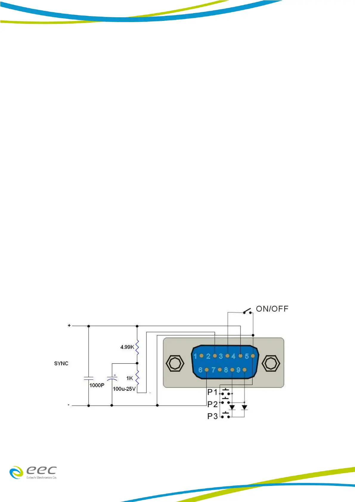
Below is the Pin Configuration of Remote:
1. ON/OFF Connect between PIN 3 and PIN 5
2. Memories Input Control can be achieved by using Normally Open (N.O) Momentary Button and
the connection as:
a Memory 1 (P1) Connect between PIN 5 and PIN 8
b Memory 2 (P2) Connect between PIN 5 and PIN 9
c Memory 3 (P3) Connect PIN 8 and PIN 9 with a series diode (ex. D4148) at each pin and
the joint point is connected to PIN 5.
3. SYNC Connect PIN 4 and PIN 6 with a series capacitor and resistance.
PLC Remote