HARDWARE INSTALLATION
10 9
HARDWARE INSTALLATION
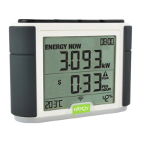
The display for your efergy monitor may be wall mounted at a convenient location. It may
also be taken in hand throughout your home to determine how much different electrical loads
consume. All efergy monitors update every ten seconds so you can apply any new load and
watch for the change in the reading on your display.
MONITOR INSTALLATION CONSIDERATIONS
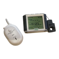
2. Plug the C T sensors’
jacks into the transmitter
1. O pen and place one
CT sensor around each
mains cable
Do not touch below this level
.
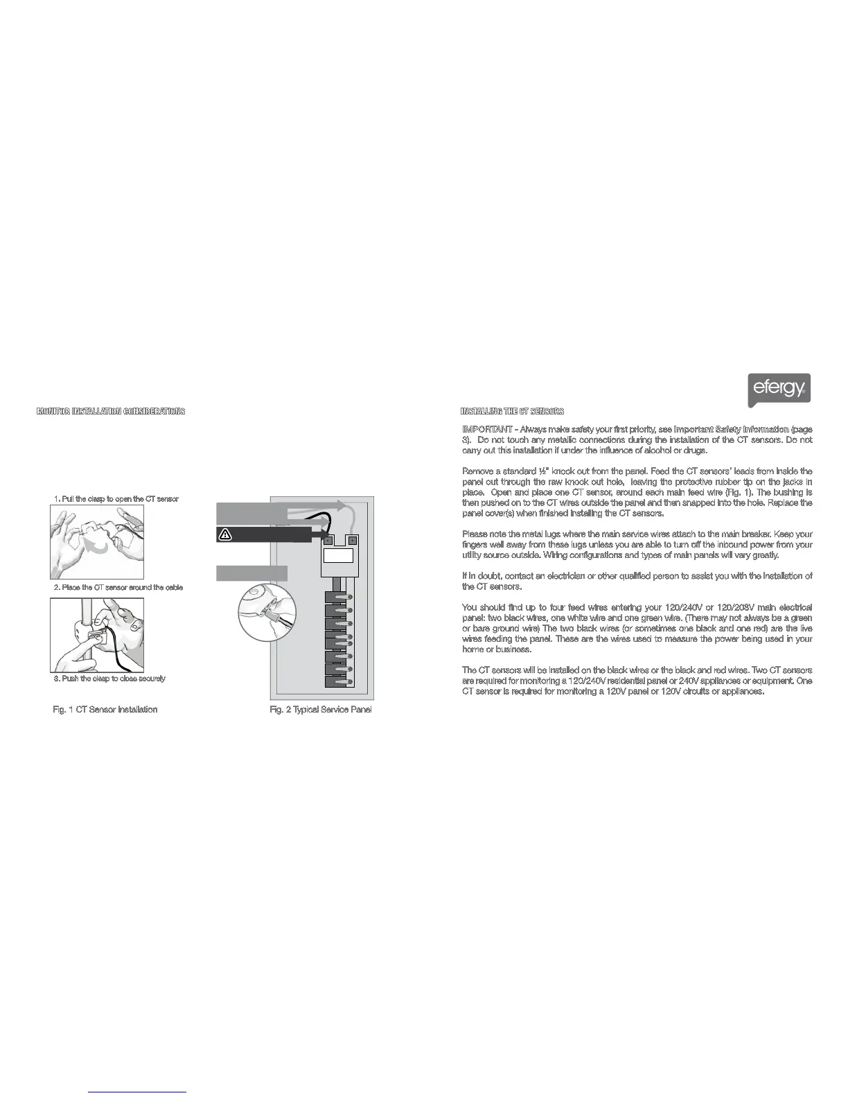
1. Pull the clasp to open the CT sensor
2. Place the CT sensor around the cable
3. Push the clasp to close securely
Fig. 2 Typical Service PanelFig. 1 CT Sensor Installation
INSTALLING THE CT SENSORS
IMPORTANT - Always make safety your first priority, see Important Safety Information (page
3). Do not touch any metallic connections during the installation of the CT sensors. Do not
carry out this installation if under the influence of alcohol or drugs.
Remove a standard ½” knock out from the panel. Feed the CT sensors’ leads from inside the
panel out through the raw knock out hole, leaving the protective rubber tip on the jacks in
place. Open and place one CT sensor, around each main feed wire (Fig. 1). The bushing is
then pushed on to the CT wires outside the panel and then snapped into the hole. Replace the
panel cover(s) when finished installing the CT sensors.
Please note the metal lugs where the main service wires attach to the main breaker. Keep your
fingers well away from these lugs unless you are able to turn off the inbound power from your
utility source outside. Wiring configurations and types of main panels will vary greatly.
If in doubt, contact an electrician or other qualified person to assist you with the installation of
the CT sensors.
You should find up to four feed wires entering your 120/240V or 120/208V main electrical
panel: two black wires, one white wire and one green wire. (There may not always be a green
or bare ground wire) The two black wires (or sometimes one black and one red) are the live
wires feeding the panel. These are the wires used to measure the power being used in your
home or business.
The CT sensors will be installed on the black wires or the black and red wires. Two CT sensors
are required for monitoring a 120/240V residential panel or 240V appliances or equipment. One
CT sensor is required for monitoring a 120V panel or 120V circuits or appliances.
Shop for Power Metering products online at:
1.877.766.5412
www.PowerMeterStore.ca