U S E R M A N U A L E P S - D
Technical specifications and data are subject to change without any prior notice.
7
24 Volt output
- EPS-Digital has a Volt output placed on terminals JP1 and JP2.
- This DC output is a low power output, and not designed to power
any external loads.
- The output is isolated from the systems internal 24 Volt power
supply.
24 Volt input
- There are 4 seperate inputs that can be used to activate or
deactivate the load. The inputs are called ”Fire Alarm” / ”Energy
Save” / ”Sub C” / Test.
- The inputs located on terminals JP1 and JP2.
- The inputs are controlled by 24 Volt. Both external or internal
power can be used for the inputs.
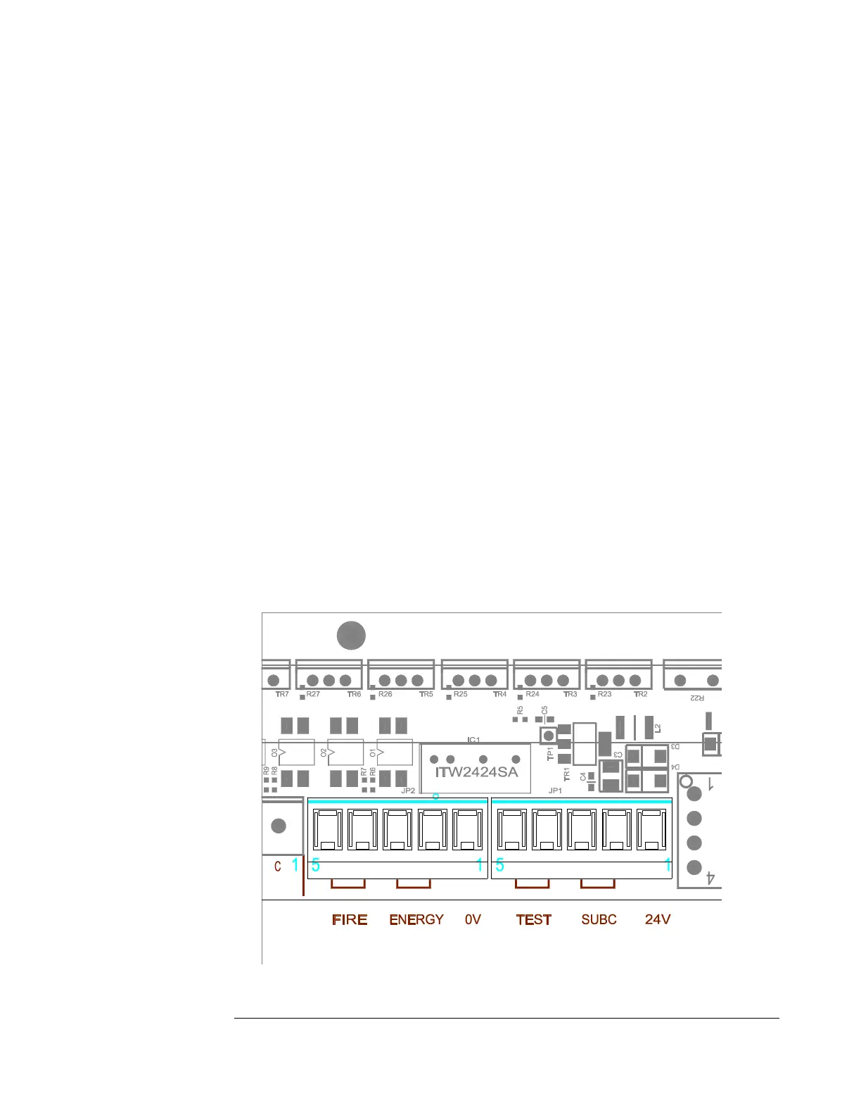
Configuration:
24 Volts Low Power Output - JP1 pin 1 and JP2 pin 1
SUBC – Sub Central Input - JP1 pin 2 and JP1 pin 3
TEST – Test Input - JP1 pin 4 and JP1 pin 5
ENERGY – Energy Save Input - JP2 pin 2 and JP2 pin 3
FIRE – Fire Alarm Input - JP2 pin 4 and JP2 pin 5