Electronic device DMU2000 - DMU3000 - DMU3000 PLUS
Electronic device DMU2000 - DMU3000 - DMU3000 PLUS
69
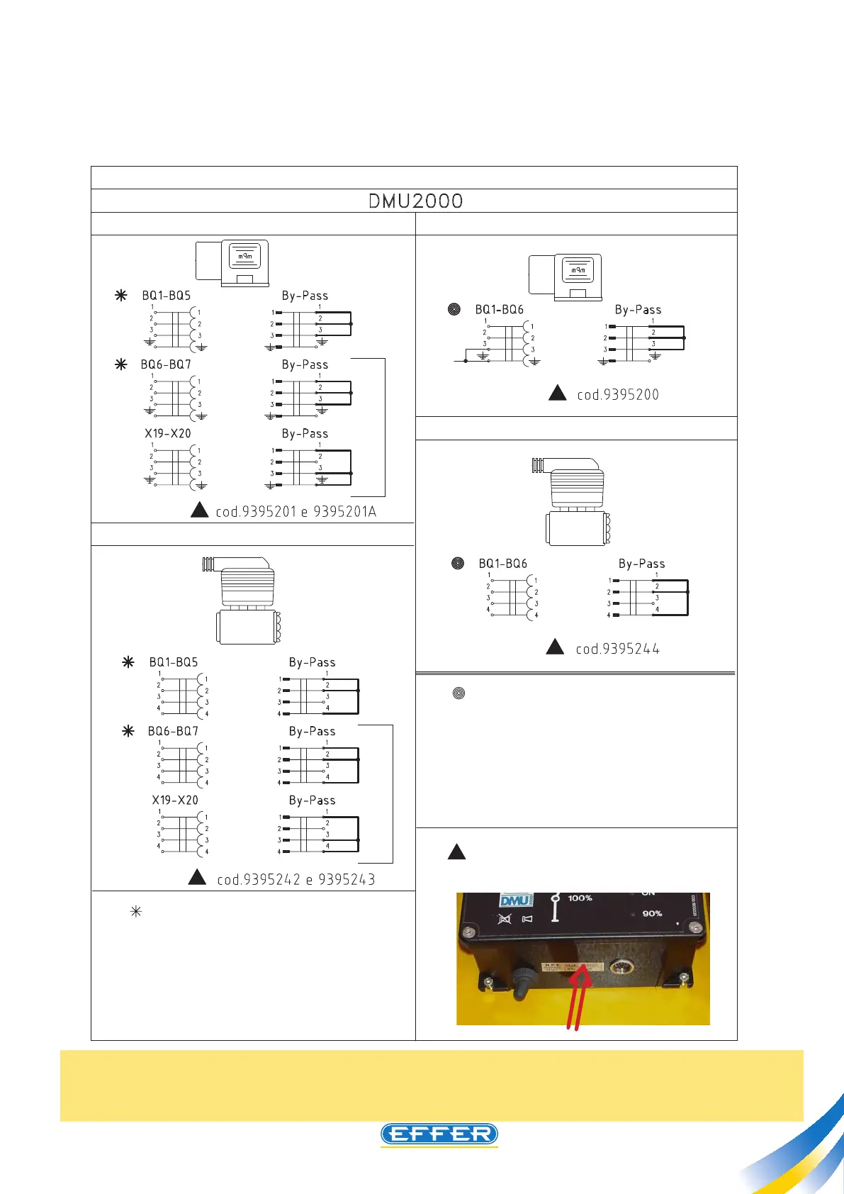
SIMULATING CONTROL BANK LEVER POSITION MICROSWITCH
In order to check control bank lever position microswitches, by-pass wires (on the connector) by bridging the posi-
tive pin and the two return signal pins, as shown in the following diagram:
NOTE: the electric connection of wires to the corresponding feeding pins (module electric supply, posi-
tive wire and negative wire) must be kept activated for cranes equipped with Danfoss control bank and
radio remote control (in case you need to operate the crane temporaneously by remote radio control).
BQ1 = CRANE SLEWING DRIVE
BQ2 = 1ST BOOM DRIVE
BQ3 = 2ND BOOM DRIVE
BQ4 = STANDARD CRANE EXTENSION DRIVE
BQ5 = WINCH DRIVE
BQ6 (X19) = CS1 SUPPL. CONTROL DRIVE
BQ7 (X20) = CS2 SUPPL. CONTROL DRIVE
WIRE MARKING / CRANE FUNCTION
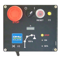
ITEM CODE PRINTED ON THE LOWER SIDE OF THE DMU
MAIN BOX
BQ1 = CRANE SLEWING DRIVE
BQ2 = 1ST BOOM DRIVE
BQ3 = 2ND BOOM DRIVE
BQ4 = STANDARD CRANE EXTENSION DRIVE
BQ5 = WINCH DRIVE
BQ6 (X19) = WINCH / CS1 SUPPL. CONTROL DRIVE
BQ7 (X20) = CS2-CS1 SUPPL. CONTROL DRIVE
WIRE MARKING / CRANE FUNCTION
CONTROL BANK TYPE HAWE
CONTROL BANK TYPE DANFOSS
CONTROL BANK TYPE HCD
CONTROL BANK TYPE NORDHYDRAULIC
ALTERNATIVE
ALTERNATIVE
CONTROL BANK LEVER MICROSWITCH BY-PASS
Direction 1
Direction 2
Negative
Positive
Direction 1
Direction 2
Negative
Positive
Direction 1
Direction 2
Negative
Positive
Direction 1
Direction 2
Negative
Positive
Direction 1
Direction 2
Negative
Positive
Direction 1
Direction 2
Negative
Positive
Direction 1
Direction 2
Negative
Positive
Direction 1
Direction 2
Positive
Positive