EFKA DA320G5351
8
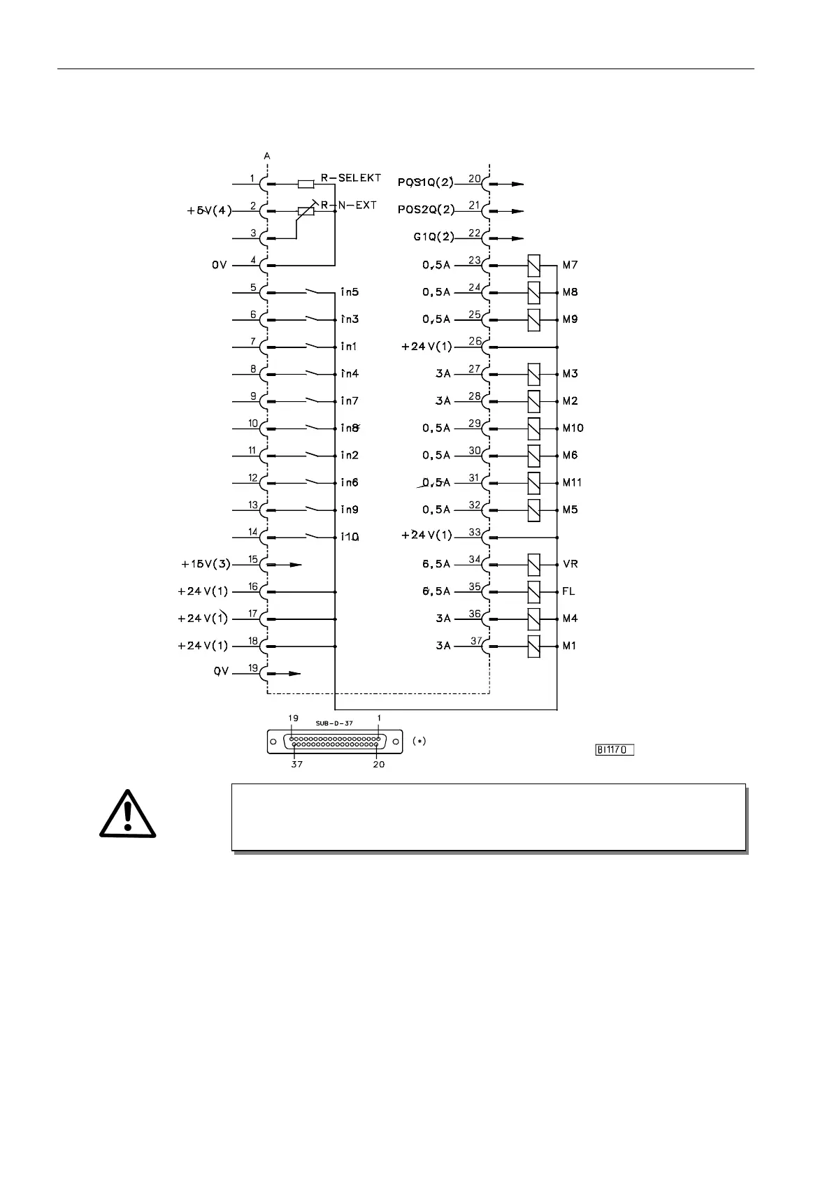
3.3 Connection Diagram
Socket ST2 corresponds to socket A
in1 - Key for output B i10 - Backtack suppression/recall M9 - LED righthand thread monitor
in2 - Machine run blockage M1 - Thread trimmer M10 - LED for output A
in3 - Needle up/down M2 - Needle cooling M11 - LED for output B
in4 - Key for output A M3 - Thread wiper FL - Sewing foot lifting
in5 - Intermediate backtack M4 - Thread tension release VR - Backtacking
in6 - Thread monitor M5 - Output B POS1 - Position 1
in7 - DB2000 M6 - Output A POS2 - Position 2
in8 - DB3000 M7 - LED lefthand thread monitor GEN - Generator impulses
in9 - External light barrier M8 - LED backtack suppression/recall R-N-EXT - External potentiometer for
speed limitation (50kΩ)
1) Nominal voltage 24V, no-load voltage max. 30V momentarily after power on
2) Transistor output with open collector (max. 40V, 10mA)
3) Nominal voltage 15V, I
max
= 30mA
4) Nominal voltage 5V, I
max
= 20mA
*) Front view of the socket (component side) and/or rear view of the plug (soldering side)
ATTENTION!
When connecting the outputs, ensure that a total power of 96VA constant load will not
be exceeded!