GB
- 79 -
•
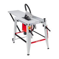
Warning! When in use, the stop rail (23) must always be screwed
to the side of the parallel stop (7) which faces the saw blade.
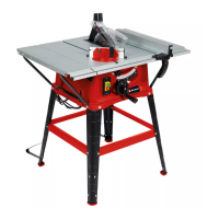
7.3.2. Cutting width (Fig. 17)
•
The parallel stop (7) can be mounted on either side of the saw
table (1).
•
The parallel stop (7) has to be mounted in the guide rail (28) of
the saw table (1).
•
The parallel stop (7) can be set to the required dimension with
the help of the scale (22) on the guide rail (28).
•
You can clamp the parallel stop in the required position by pres-
sing the eccentric lever (12).
7.3.3. Setting the stop length (Fig. 17, 18)
•
The stop rail (23) can be moved in longitudinal direction in order
to prevent the workpiece from becoming jammed.
•
Rule of thumb: The rear end of the stop comes up against an
imaginary line that begins roughly at the center of the blade and
runs at an angle of 45° to the rear.
•
Set the required cutting width
- Slacken the knurled screws (26) and push the stop rail (23) for-
ward until it touches the imaginary 45° line.
- Retighten the knurled screws (26).
Warning! The gap between the saw table (1) and the underside of
the stop rail (23) must not be too large in order to prevent the ma-
terial getting jammed. To adjust the distance, the parallel stop (7)
must be fastened fi rst using the eccentric lever (12). Then slacken
the knurled screws (26), lower the stop rail (23) down to the saw ta-
ble (1) and secure the knurled screws (26) again afterwards.
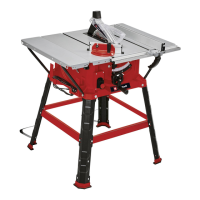
7.4 Cross stop (Fig. 20)
The cross stop (14) has to be used when making cross cuts in woo-
den workpieces.
•
Slide the cross stop (14) into the slot (21) of the saw table.
Anl_TC_TS_2225_U_SPK7_Rewe.indb 79 24.03.2020 10:29:26