TECNOEKA Srl ___________________________________________________________ operating and instruction manual
page 46 _____________________________________________________________________________________________
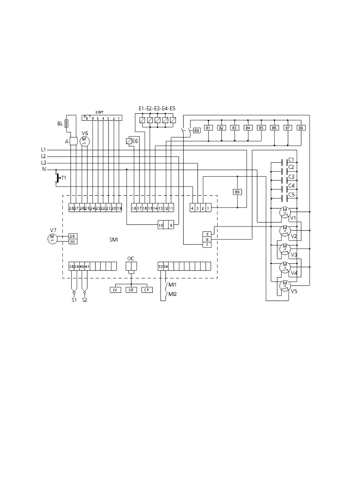
MODELS EKF 1664 TC – EKF 2011 TC
Control diagram
M Power supply terminal board
L1 Line 1 Phase Terminal
L2 Line 2 Phase Terminal
L3 Line 3 Phase Terminal
N Neutral Terminal
B1-B2-B3-B4-B5-B6-B7-B8 Contactor coils
R1-R2-R3-R4-R5 Circular resistors
E1-E2-E3-E4-E5 Water solenoid valves
C1-C2-C3-C4-C5 Capacitors
V1-V2-V3-V4-V5 Radial motorfans
B9 Relay coil
V6-V7 Cooling motorfans
A LED Bar Power Supply Unit
BL LED Bar
T1 Safety thermostat
MI Door microswitch
S1 Cooking chamber probes
S2 Food “core” probe
SMI Microprocessor board
SD Display board