Packing List
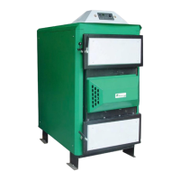
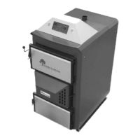
The complete EKO Orlan boiler is shipped from the warehouse in one crate.
Inside the crate you will find:
The boiler.
The cleaning tools (two or three, depending on the model).
Inside the boiler you will find:
This manual.
Refractory gasification bricks (two or more pieces that form a tunnel under the nozzle or nozzles).
Boiler Set-Up
The boiler is shipped completely assembled and ready for installation and use. The boiler should be
inspected inside and out for any defects or damage that may have occurred in shipping. After the
boiler is placed in its permanent location and before the first firing, the refractory tunnel will need to be
positioned directly under the nozzle or nozzles, so that the flame shoots directly down into the trough.
Piping
The direct connections to the boiler will be similar no matter which piping system you select (page
12). A detailed listing of pipe fittings, isolation valves, etc. is not part of this manual. If you have ques-
tions about designing your system, seek the advice of a hydronic heating professional.
However, some important piping considerations are included below:
A tee must be connected to the 2” NPT water inlet on the rear bottom of the boiler (return). In one port
of the tee install a drain valve that is piped to a floor drain. In the other port of the tee install a line to
the outlet of the circulating pump, upon which the inlet is connected to the outlet port of a 3- or 4-way
mixing valve. One inlet of the mixing valve is fed from the heat zone piping return lines. The other
inlet of the mixing valve is fed from a tee connected to the boiler outlet and the heat zone supply line.
The purpose of this valve is to prevent cold water from entering the boiler, which can result in thermal
shock causing mechanical warping and cracking, as well as creating condensation inside the firebox,
which will result in corrosion inside the boiler.
Connect another tee to the 2” NPT water outlet on the top of the boiler (supply). In one port of the tee
install the supplied pressure relief valve. Be sure to pipe the outlet of this valve with hard pipe (copper
or black iron) to within 6 inches of the floor, and be sure there are no shut-off valves or other obstruc-
tions on the pipe. When this relief valve opens, it means that the boiler pressure has reached or
exceeded 30 pounds per square inch. The steam and/or water released needs to flow freely and the
pipe must be no more than 6 inches from the floor to prevent injury to anyone nearby. In the other port
of the tee install a line to the tee connected to the boiler outlet and the heat zone supply line.
Connect a line from the building water supply through a back flow preventer valve to the boiler INLET
line. Water should only be introduced to the boiler when its temperature is below 160F.
There is a 3/4” NPT pipe sticking out each side of the boiler near the top. This is an emergency boiler
cooling system not used in North American installations. The outlets can be covered with 3/4” NPT
pipe caps with a 1/4” diameter hole drilled in each one. The caps cover the sharp threads and the
holes keep pressure from building up in the pipe during boiler operation. This system is independent
from the pressure vessel, so there is no boiler water involved.