Photocells
The photocells are in pairs, one transmitter and one receiver. They should be mounted 500-600 mm from the
ground and face each other level. Each photocell regardless of type has a 24VAC supply.
The receiving photocell does the switching on and off to the control panel. If the transmitting beam can reach the
receiving photocell, there will be a completed circuit to the main panel and the gate/s will function. If the beam is
broken, during operation of closing, the gates will stop and reopen.
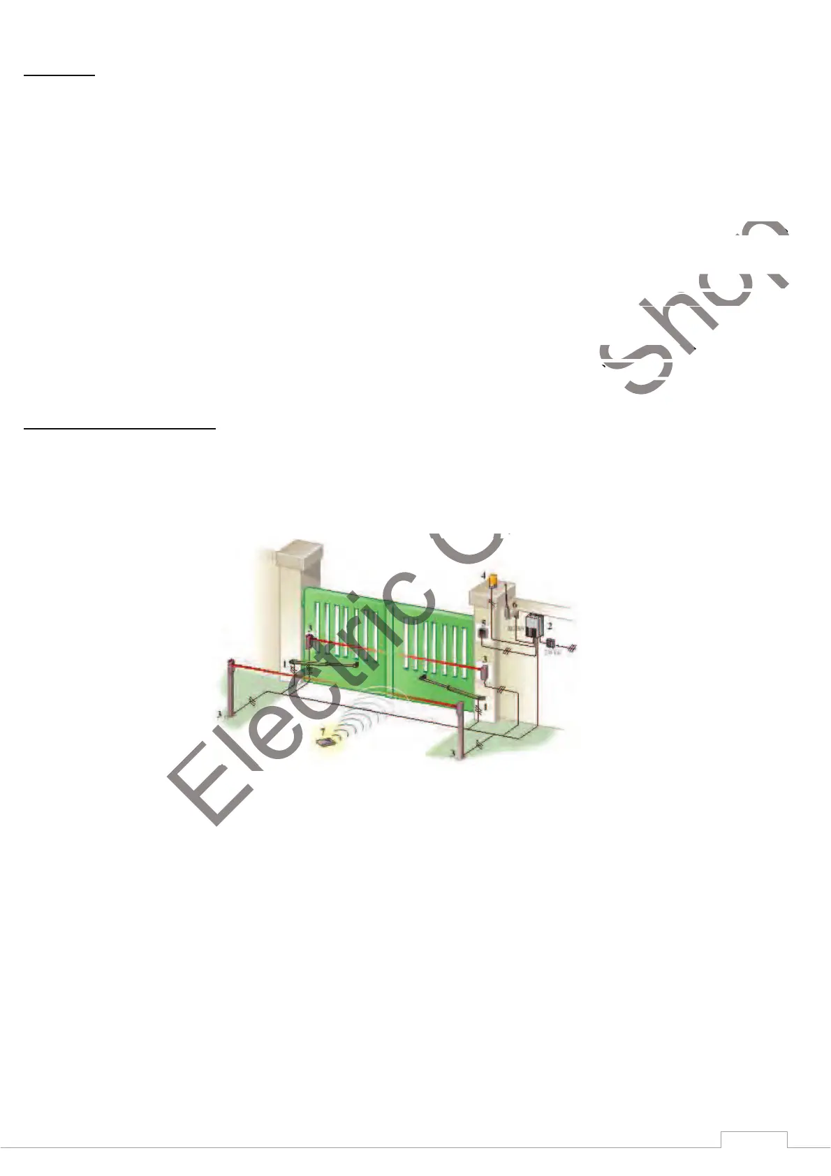
If you are using two pairs of photocells as pictured, the receivers should be crossed on opposite sides so that you
do not have two receivers at the same side.
For this purpose 4 core BT type cable is recommended for use. (CW1128) Follow the wiring diagram provided to
wire both the receiver and transmitting photocells. At the control box end, wire the colour coded cables up as per
the diagram provided showing a typical photocell placement.
When the photocells are working and correctly aligned, you should hear a clicking sound from the transmitter when
the beam is broken intermittently. Once wired, place the covers over the photocells and secure the fixing screw.
Fill any cable gaps with silicone to prevent insects from entering the device and interfering with it.
Surface Mounted Photocells
wire both the receiver and transmitting photocells. At the control box end, wire the colour coded cables up as per wire both the receiver and transmitting photocells. At the control box end, wire the colour coded cables up as per
the beam is broken intermittently. Once wired, place the covers over the photocells and secure the fixing screw. the beam is broken intermittently. Once wired, place the covers over the photocells and secure the fixing screw.