Programming the 909 circuit board
Before you start to programme!
Check that the gate wing stops are in place and set! If you are using motors with inbuilt electric limit switches, move these so
they are not operational for the purpose of the test (NC). They can be re-introduced after the set up is completed
Check that you have wired the photocells correctly and bridged (linked) the normally closed (N.C) circuits that are not being
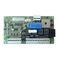
used. If you have done this correctly, you should have these LEDs illuminated with the power to the circuit board on.
The first two LEDs from the left should only appear when
a open command or a pedestrian command is given. If the fourth
from the left LED is missing check your photocell wiring circuit and alignment of the beams. If any other LEDs marked ON are
not illuminated, check the circuits or the links outlined on the typical wiring diagram page.
STEP1 Programming the remotes
*Note* Carry out programming the remotes only with the aerial disconnected from the PCB. This avoids picking up stray frequency codes from
other equipment. Reconnect only when you have finished programming the remote control equipment.
STEP4 Verify motor direction
You need to verify that the motors are going in the right direction in relation to the panel. Arrange gate’s so that they are both approximately
half way. Turn the power off to the panel. (It is important that you leave the power off to the panel at least 15 seconds or the fuse may fail
when you turn back on the power) Turn the power back on again. Press once the key fob that you previously learned in at step 2 and 3.
Observe the direction that both gates move in at the start and then immediately turn the power off again. The gate that travels in an open
direction is correct. The gate that travels in a closing direction is incorrect. Identify this motor at the PCB as M1 or M2 and these motor wires
need swapping with each other. Remember, the gate that you want to open first should be connected to M1 or with a single gate use M1.
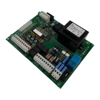
STEP1 with KW113 remote,
open the cover and randomly arrange the
dip-switches first.
STEP3.
While the DL6 is flashing,
press and hold the button
on your remote you want
to open the gate fully for 3
seconds.
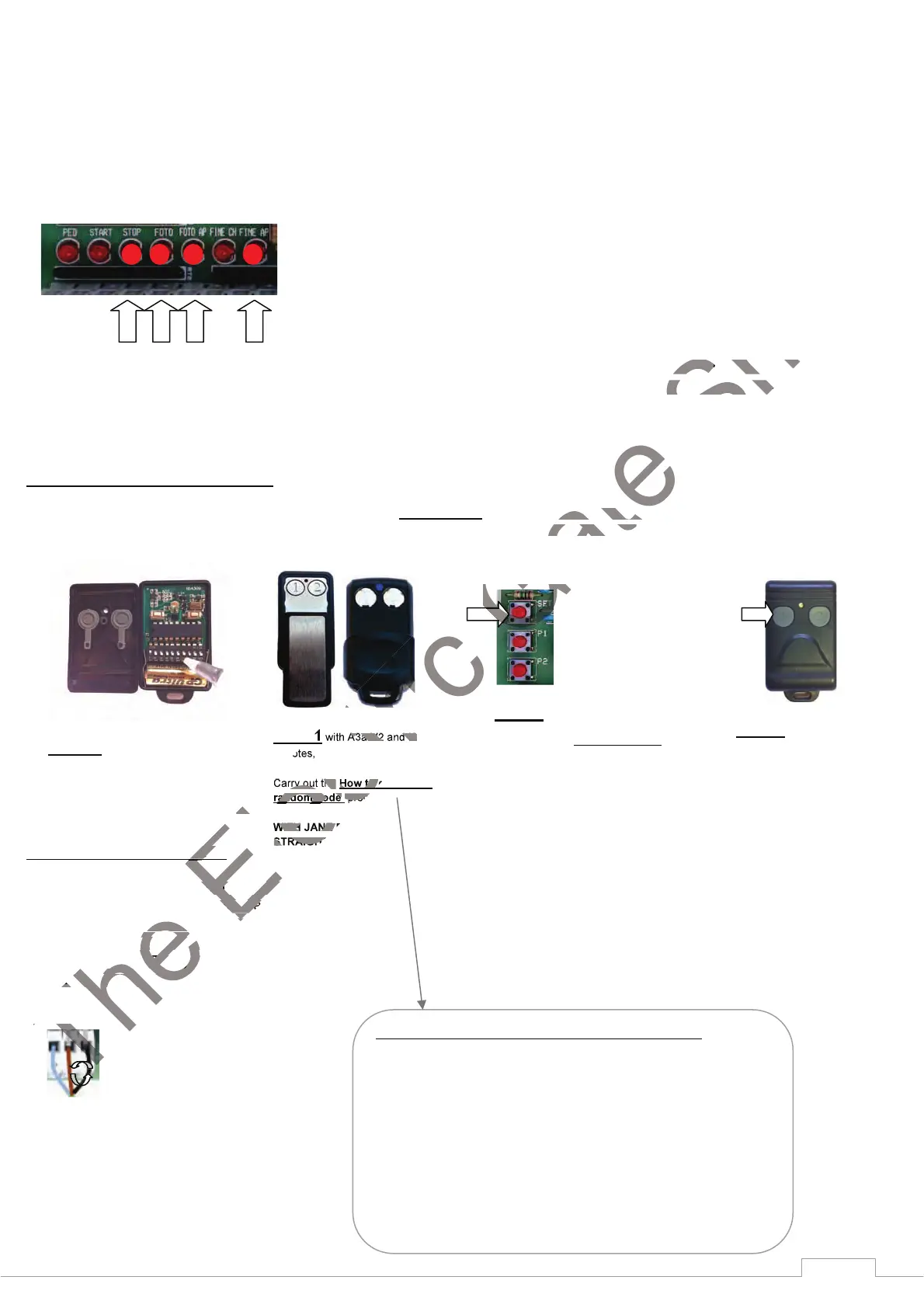
STEP2
Enter radio code programming (for the
START control). Press and release
the SET. button once, the LED DL3
will start to flash. Go to STEP3 The
board accepts the code and exits from
programming (DL3 turns off). It is
possible to store up to a maximum of
32 different codes for the START
control.
O
N
O
N
O
N
O
N
STEP1 with A3a-V2 and I8
remotes,
Carry out the How to generate a
random code procedure.
WITH JANE REMOTES GO
STRAIGHT TO STEP 2
How to generate a random fob code for A3a-V2 and I8 Remotes
Press and hold button (1)
Keep button (1) pressed then press and hold button (2) (The led flashes slower)
Keep both buttons pressed for 15 seconds (The led will start to flash faster).
Whilst still holding in buttons (1) & (2), Release button (1) wait 2 seconds and
release button (2).
You have now generated a random code in both buttons.
This code can now be learned to the radio receiver card.
 Loading...