03/2013 - Art. Nr. 4200 1032 7200A 3
Overview
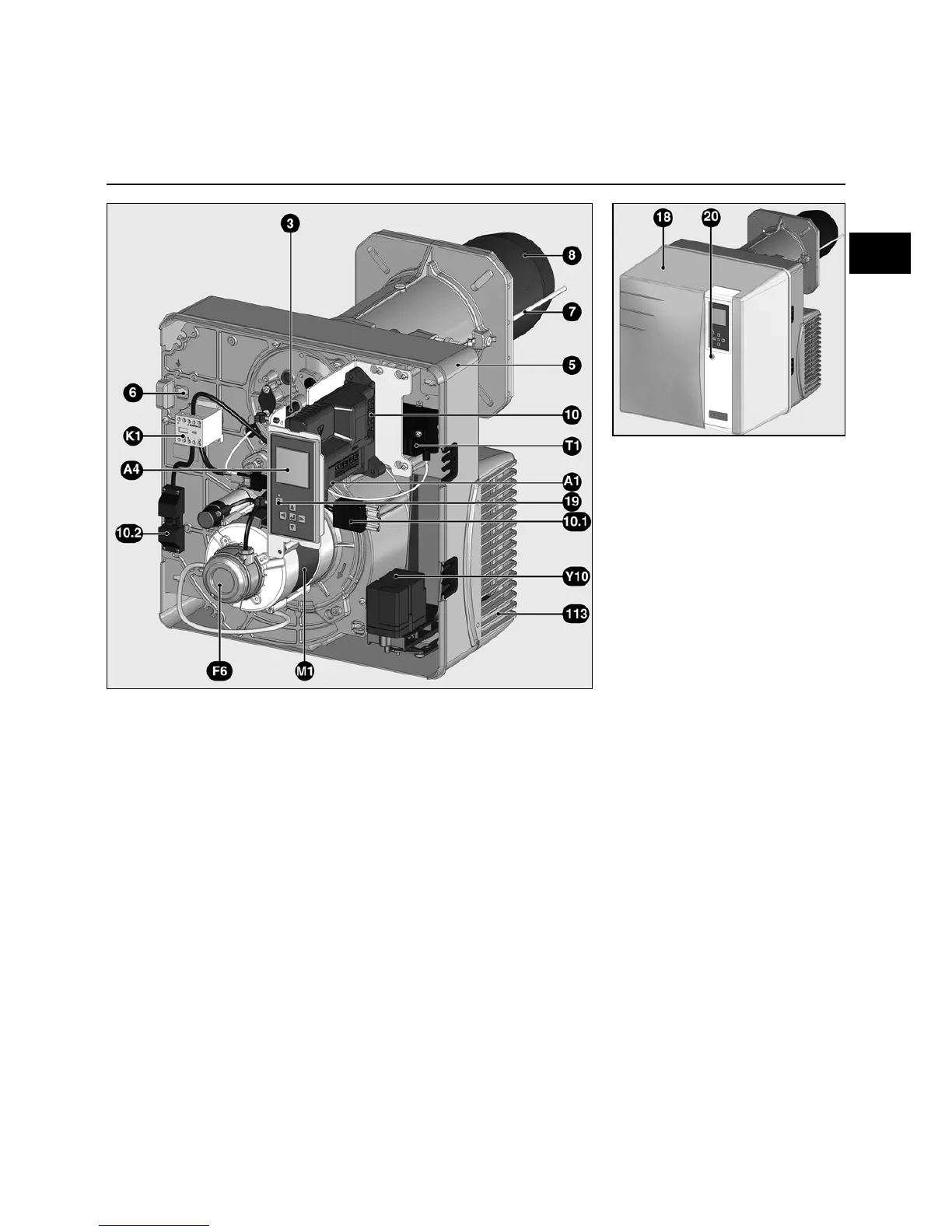
Burner description
A1 Control and safety unit
A4 Display
F6 Air pressure switch
K1 Auxiliary motor supply relay
M1 Blower motor
T1 Igniter
Y10 Air flap servomotor
3 Adjusting screw for dimension Y
5 Housing
6 Plate hanging device
(Maintenance)
7 Combustion chamber pressure
take-off pipe
8 Burner tube
10 7-pin connector
10.1 4 pin connector
10.2 3-pin connector (auxiliary motor
supply relay)
18 Cover
19 Release knob
20 Hood securing screw
113 Air intake box

 Loading...