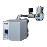
Checking the burner head
• Check the adjustment settings of the
ionisation probe and of the ignition
electrode as per the diagrams.
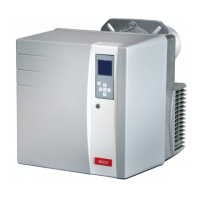
Setting to liquid gas operation
• Remove the gas diffuser 5 and the
turbulator 2.
• Remove adaptor 3.
• Fit the adaptor 6 (supplied with the
housing) on the gas burner head.
• Turn the gas diffuser 5 180° and refit it.
• Refit the turbulator 2 and the 3 spacers
4, using the 3 new screws 1 provided.
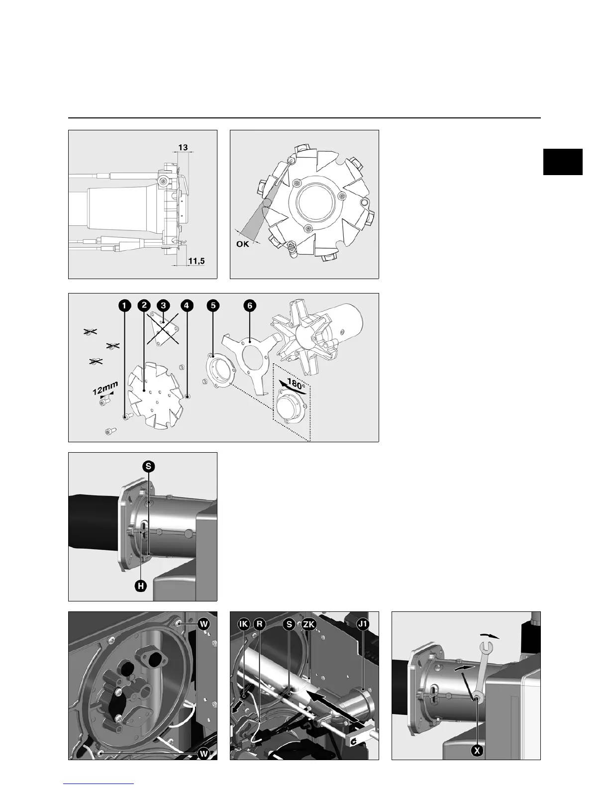
Assembly
Checking/adjusting the burner head
Check the radial position of the flame
tube
After untightening the three mounting
screws S, it is possible to change the
position of the flame tube using the lever
H. Nitrogen oxide emissions may be
affected by the radial position of the
flame tube
• To be set at the start to position 1.
Fitting the combustion components
• Check that the O-Ring J1 is in the
correct position in the gas elbow.
• Insert the combustion components
into the head, tighten the mounting
screw X using an Allen key, then
tighten the lock nut using an open-
ended spanner.
• Thread the ionisation cable IK and the
ignition cables ZK into the grommets
R and S.
• Remove the cover.

 Loading...