8
3.4 MEASURING CONNECTIONS
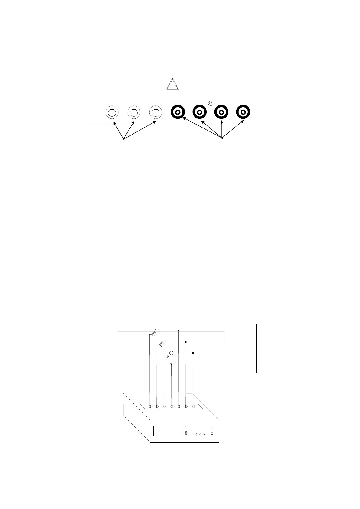
The connectors for use in voltmeter and ammeter connections are located in the top of the instrument.
Follow these instructions carefully to avoid measurement errors.
3.4.1 VOLTMETER CONNECTIONS
Use the cables supplied for the purpose in the kit.
3.4.2 CURRENT MEASURING CONNECTIONS
Use the clamp meters supplied for the purpose in the kit.
When making current measurement make absolutely sure that each clamp meter is connected to the same phase
as the corresponding voltage measurement.
Incorrect connections can give rise to significant measuring errors since a phase angle between current and voltage of
120 degrees can be added.
When connecting the clamp meters with Std1 or Std2 option selected, you do not need to know the direction of flow
since the instrument automatically inverts in case of reversed connections.
The following diagram (fig. 3.2) shows the correct connection layout.
LOAD
(T) L3
(S) L2
(R) L1
Fig. 3.2
INPUT CURRENT
1 L2 L3
INPUT VOLTAGE
N L1 L2 L3
Connectors for
current measurements
Connectors for
voltage measurements