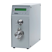
4
An Overall Look at the Local Interface
Operation of the Optos Pump is controlled from a series of menus and there is no need to remember esoteric
control codes or command sequences. A detailed description of the menu sequence is given in Section III.
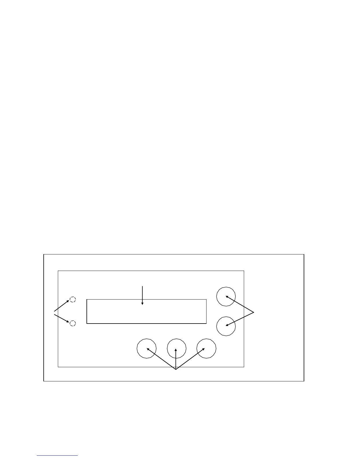
As you look at the local interface (Figure 1.3), you will see:
Component Details
1. Status LEDs: Upper green LED indicates pump is running; lower red LED indicates a pump fault (for
example, an overpressure limit, or motor stall condition.
2. Display: A one line, 16 character LCD display is used to provide readout of flow and pressure (with
optional pulse damper), and access to pump functions.
3. Up/Down Keys: UP and DOWN arrow keys set flow rates, pressure limits (with optional pulse damper),
and function settings.
4. Permanent Function Keys: ΔMENU key changes the display to different pump functions, DISPLAY key
toggles display back to main display of flow, or flow and pressure (with optional pulse damper),
RUN/STOP key runs the pump and stops the pump.
Key Definitions
ΔMENU: The ΔMENU (Change Menu) key scrolls through the main menu selections.
DISPLAY: The DISPLAY key toggles back to main display of flow, or flow and pressure (with optional pulse
damper).
UP/DOWN: UP and DOWN arrow keys increase or decrease flow rate setting, high or low pressure limit settings,
and change setting of other pump parameters.
DISPLAY, then ΔMENU: Holding down the DISPLAY key followed by pressing the ΔMENU key brings up a series
of sub menus which pertain to various pump settings. Pressing the DISPLAY key alone returns to main display.
ΔMENU, then DISPLAY: Holding down the ΔMENU followed by pressing the DISPLAY key brings up a series of
sub menus which pertain to obscure pump settings. Pressing the DISPLAY key alone returns to main display.
Figure 1.3: Local Interface