PROG
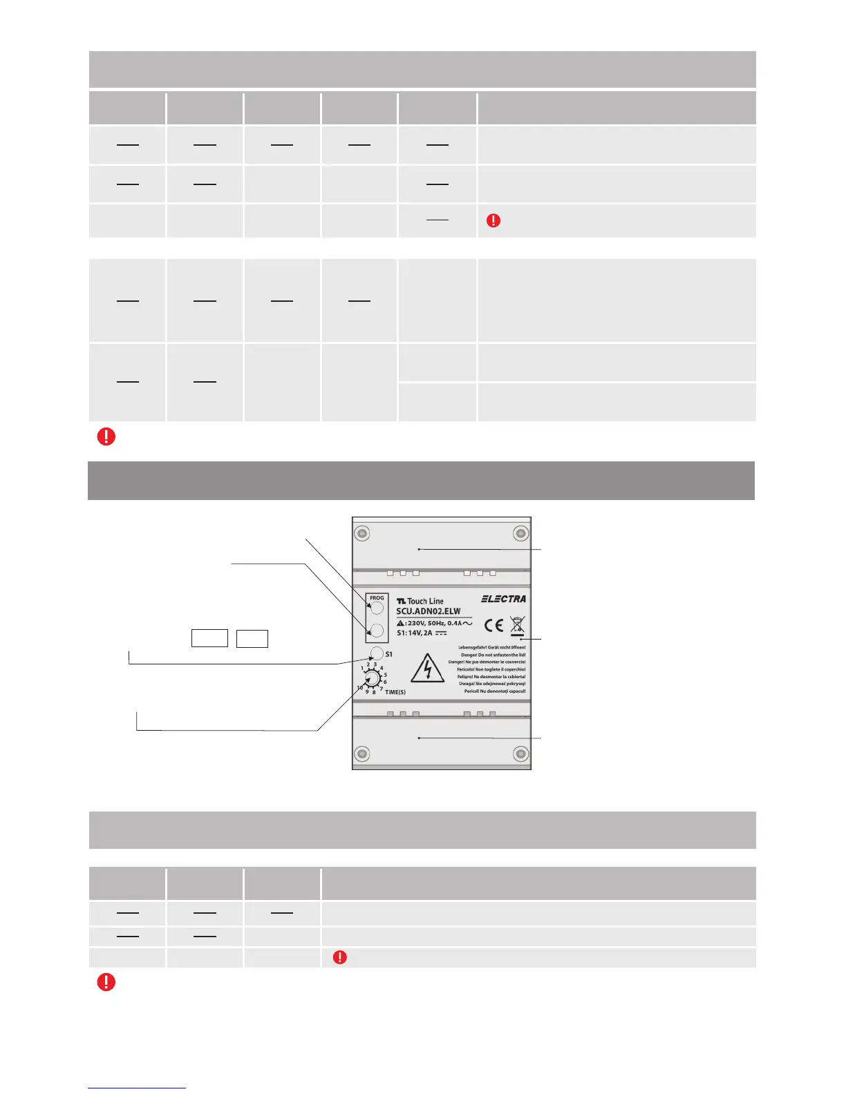
SUPPLY CONTROL UNIT (SCU.ADN02.BLW)
Lock
timing
(seconds)
INPUT: 230V alternating current 50Hz, 0.4A
OUTPUT: 14V, 2A direct current (S1)
10
1
2
3
4
5
6
7
8
9
S1
CAUTION! DO NOT
UNFASTEN THE SAFETY LID!
RISK OF
ELECTRICAL SHOCK!
Long press
RED
GREEN GREEN
Programming mode
BUTTON
PROG
LED
PROG
LED
S1
LED
S2
LED
S3
The system is not connected to the 230 Va.c./
50 Hz network.
The system is OK, connected to the 230 Va.c./
50 Hz network.
Significance of LEDs signaling
GREEN GREEN
The system is not connected to the 230 Va.c./
50 Hz network. The battery is functional.
The system works only on audio and door
opening, for a limited time slot.
GREEN
GREEN
The system is OK, connected to the 230 Va.c./
50 Hz network. The battery is functional.
When a battery is connected to SCU, there are the following additional signals only for S3 LED:
GREEN
GREEN
RED
The system is OK, connected to the 230 Va.c./
50 Hz network. Battery charging or defect.
For LEDs signaling RED, see ch. 7 – Troubleshooting.
*programming button PROG.
TIME: Lock timing adjustment
(1-10 sec.)
Protection lid 1 for electrical
connections
Front lid
red LED of PROG.
(programming mode or
defect within the system)
S1: GREEN
Protection lid 2 for connections
+14V - GND
(+14V/2Ad.c.)
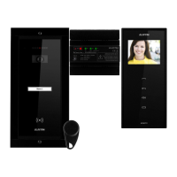
6.3.2. Audio central unit (SCU.ADN)
Long press
RED
GREEN
Programming mode.
BUTTON
PROG
LED
PROG
LED
S1
The system is not connected to the 230 Va.c./ 50 Hz network.
The system is OK, connected to the 230 Va.c./ 50 Hz network.
Significance of LEDs signaling
GREEN
For LED signaling RED, see ch. 7 – Troubleshooting.
35