1360 Page 18
Electro-Mech Scoreboard Co. • 120 Industrial Parkway • Wrightsville, GA 31096
Phone: (800) 445-7846 • Fax (478) 864-0212 • Email: score@electro-mech.com
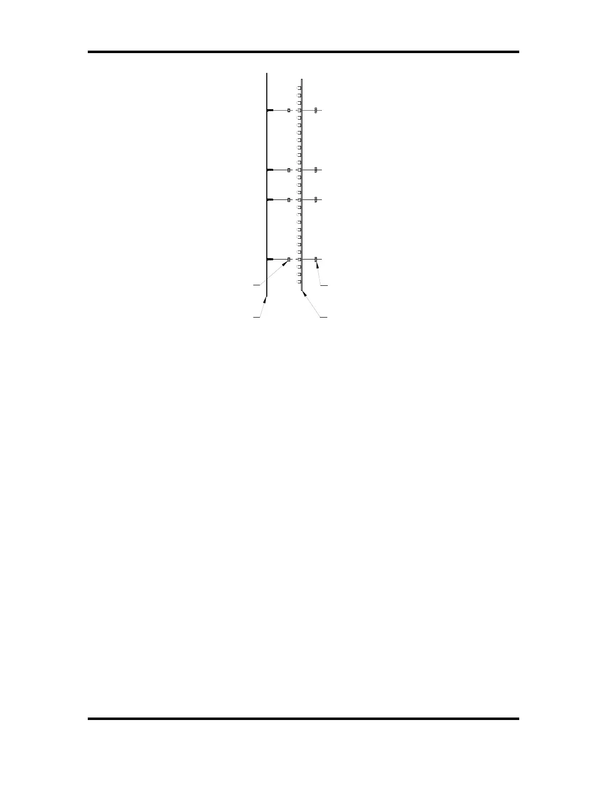
LED DIGIT
1/8" SPACER
6-32 KEP LOCK NUT
MASK
Figure 12 LED Digit Assembly
1. Remove the sheet metal screws that fasten the mask to the face of the scoreboard.
Caution: Support the mask with before removing the last screw. The ribbon
cable that connects to the rear of the circuit board is not designed to support the
weight of the assembly.
2. Disconnect the ribbon cable from the rear of the circuit board. Caution: Do not let
the cable hang outside of the scoreboard. It is easily cut by sharp metal edges.
Damage to the ribbon cable may create short circuit paths that will damage the
LED driver module.
3. Place the assembly on a flat surface and remove the 6-32 kep lock nuts that hold the
circuit board in place.
4. Remove the circuit board.
5. Align the mounting holes in the circuit board with the threaded studs on the mask and
install the replacement digit on the mask.
6. Plug the ribbon cable onto the header on the back of the circuit board. Refer to figure
13 in order to plug the ribbon cable IDC connector onto the circuit board in the proper
orientation.