1360 Page 20
Electro-Mech Scoreboard Co. • 120 Industrial Parkway • Wrightsville, GA 31096
Phone: (800) 445-7846 • Fax (478) 864-0212 • Email: score@electro-mech.com
CABLE
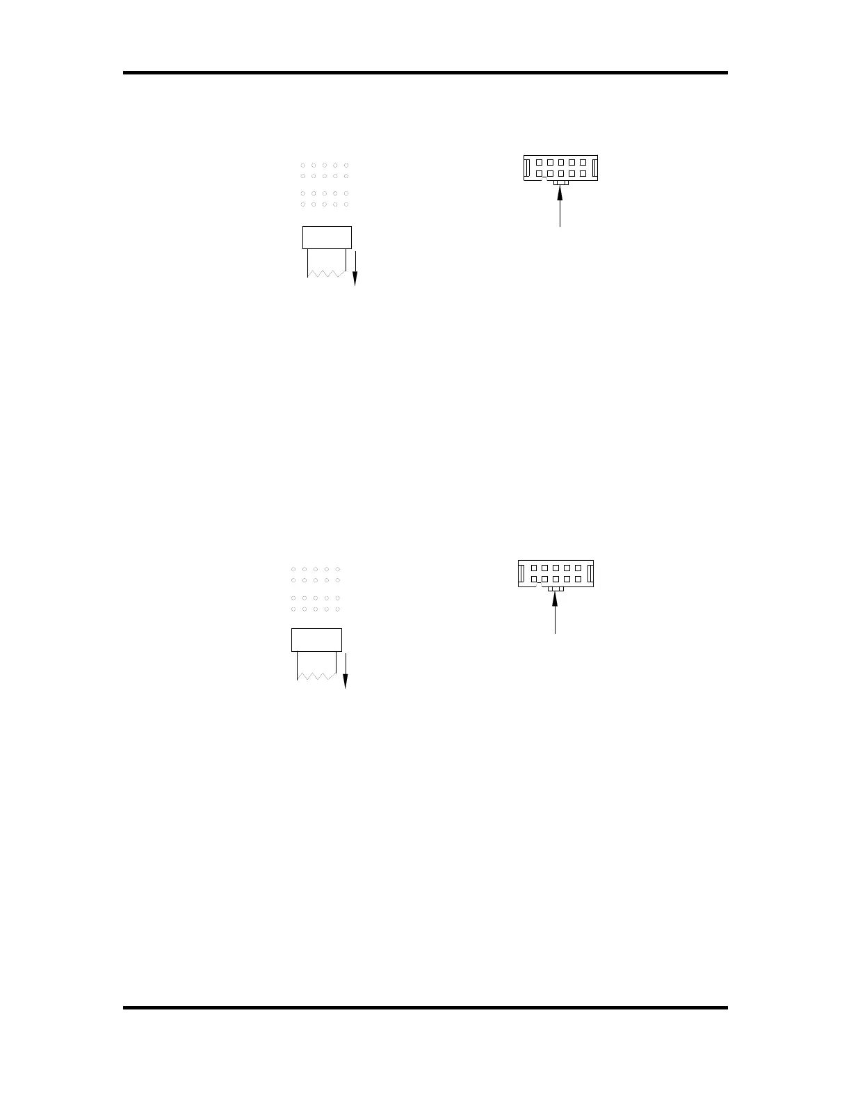
4-INCH OUTDOOR QUARTERS
3-4 BULLETS HEADERS
RIBBON CABLE
IDC SOCKET
CENTER KEY
CENTER KEY ON RIBBON CABLE IDC
SOCKET MUST POINT IN THE SAME
DIRECTION AS THE ARROW ON THE
REAR OF THE CIRCUIT BOARD.
QUARTER 3
QUARTER 4
Figure 15 Quarters 3 and 4 Indicators Ribbon Cable Connection Diagram
9. The circuit board used for the DOWN indicators has two headers. Refer to figure 16
in order to plug the ribbon cable IDC connector onto the correct header on the circuit
board in the proper orientation.
4-INCH OUTDOOR DOWNS
BULLETS HEADERS
CENTER KEY ON RIBBON CABLE IDC
SOCKET MUST POINT IN THE SAME
DIRECTION AS THE ARROW ON THE
REAR OF THE CIRCUIT BOARD.
CABLE
DOWN 3-4
DOWN 1-2
RIBBON CABLE
IDC SOCKET
CENTER KEY
Figure 16 Down Indicators Ribbon Cable Connection Diagram
All other components are located behind the rear access panel. Figure 17 shows the view
behind the access panel.