- 31 -
DGS-TDS-N07.2003 C.D. 599 51 74-13 EN
10.2 Reading the alarm codes
In order to read the last alarm code memorized in the EEPROM on the PCB:
- Enter service test programme (see page 29)
- Irrespective of the type of PCB and configuration, turn the programme selector clockwise to
the tenth position.
10.2.1 Displaying the alarm
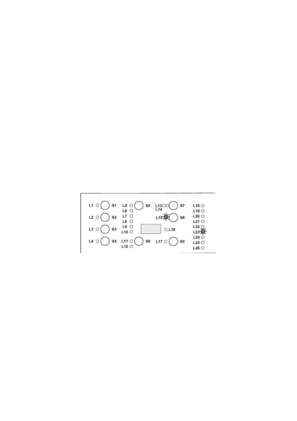
The alarm is displayed by a repeated flashing sequence of the two LEDs (0.4 seconds lit, 0.4 seconds
off, with an interval of 2.5 seconds between sequences) and in the display (if featured). The buzzer (if
featured) will sound bips in synchronization with the flashing of the END OF CYCLE-LED:
- END OF CYCLE-LED (LED 23) indicates the first digit of the alarm code (family).
- START/PAUSE-LED (LED 15) indicates the second digit of the alarm code (number within
the family).
These two LEDs are featured on all models (though they are configured differently), and flash
simultaneously.
Notes:
- The first letter of the alarm code E (Error) is not displayed, since this letter is common to all
alarm codes.
- The alarm code families are shown in hexadecimal; in other words:
A is represented by 10 flashes
B is represented by 11 flashes
...
F is represented by 15 flashes
- Configuration errors are shown by the flashing of all the LEDs (user interface not
configured).
10.2.2 Operation of alarms during diagnostics
All alarms are enabled during the components diagnostics phase.