15
Mobile home installations, new branch circuit
installations (1996NEC) or areas where local codes do
not permit grounding through neutral require a four (4)
conductor power supply cord kit rated at 125/250 volts
minimum and marked for use with ranges. See Range
Connection Opening Size Chart for cord kit ampere
rating information. Terminals on end of wires must be
either closed loop or open-end spade lugs with upturned
ends.
2B. Models Requiring Power Supply Cord Kit
RISK OF FIRE OR ELECTRICAL SHOCK MAY OCCUR
IF AN INCORRECT SIZE RANGE CORD KIT IS USED,
THE INSTALLATION INSTRUCTIONS ARE NOT
FOLLOWED OR STRAIN RELIEF BRACKET IS
DISCARDED.
This appliance may be connected by means of a power
supply cord. Only a power supply cord kit rated at 125/
250 volts minimum, and marked for use with ranges
shall be used. See chart on page 3 for cord kit ampere
rating information. Cord must have either three (3) or four
(4) conductors. Terminals on end of wires must be either
closed loop or open-end spade lugs with upturned ends.
Cord must have strain relief clamp.
See section 4A for 3-wire or section 4B for 4-wire
connection.
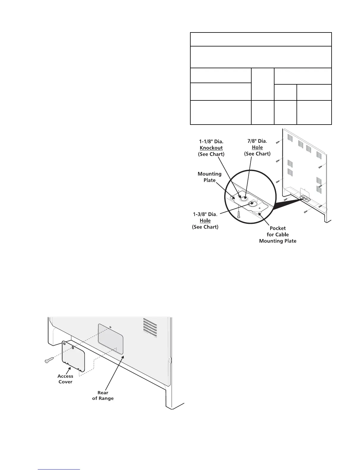
3. Electrical Connection to Range
The rear access cover must be removed. To remove,
loosen center screw (one screw) and remove access
cover. The terminal block will then be accessible.
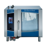
NOTE: Range is shipped from factory with 1-3/8" dia.
hole as shown. To use either 7/8" dia. hole or 1-1/8" dia.
knockouts:
If a different diameter hole is required, please
follow the steps below:
1. Using a 1/4" socket driver, remove eight (8) screws
from Rear Wall Shield to release from the unit (as
shown). Save the screws for step 7 below.
2. Again using the 1/4" socket driver, remove one (1)
blunt point screw used to secure the Cable Mounting
Plate to the Rear Wall Shield. Save the screw for
step 6.
3. Remove the Cable Mounting Plate from the Rear
Wall Shield by sliding the plate out of the pockets.
4. If a 1-1/8" dia. hole is required, "punch-out" the
knockout.
5. Rotate the plate 180 degrees so that the desired
hole is placed on top of the opening located on the
bottom flange of the Rear Wall Shield.
Range Connection Opening Size Chart
Supply Cord Kit ampere rating information. See
serial plate on Range for kilowatt rating data.
See Serial Plate on
Range for KW Rating
120/240 Volts
120/208 Volts
8.8-16.5 KW/7.9-12.5 KW
16.6-22.5 KW/12.6-18.5 KW
Cord Kit
Ampere
Rating
Diameter (in.) of Range
Connection Opening
Cord Kit
Permanent
Wiring
40/50
Amp
1-3/8 in.
1-3/8 in.
1-1/8 in.
1-3/8 in.
Access Cover