21
the range, with four displays, one for each element that
shows the setting of the control. These work as interfaces
between potentiometers and the mother board.
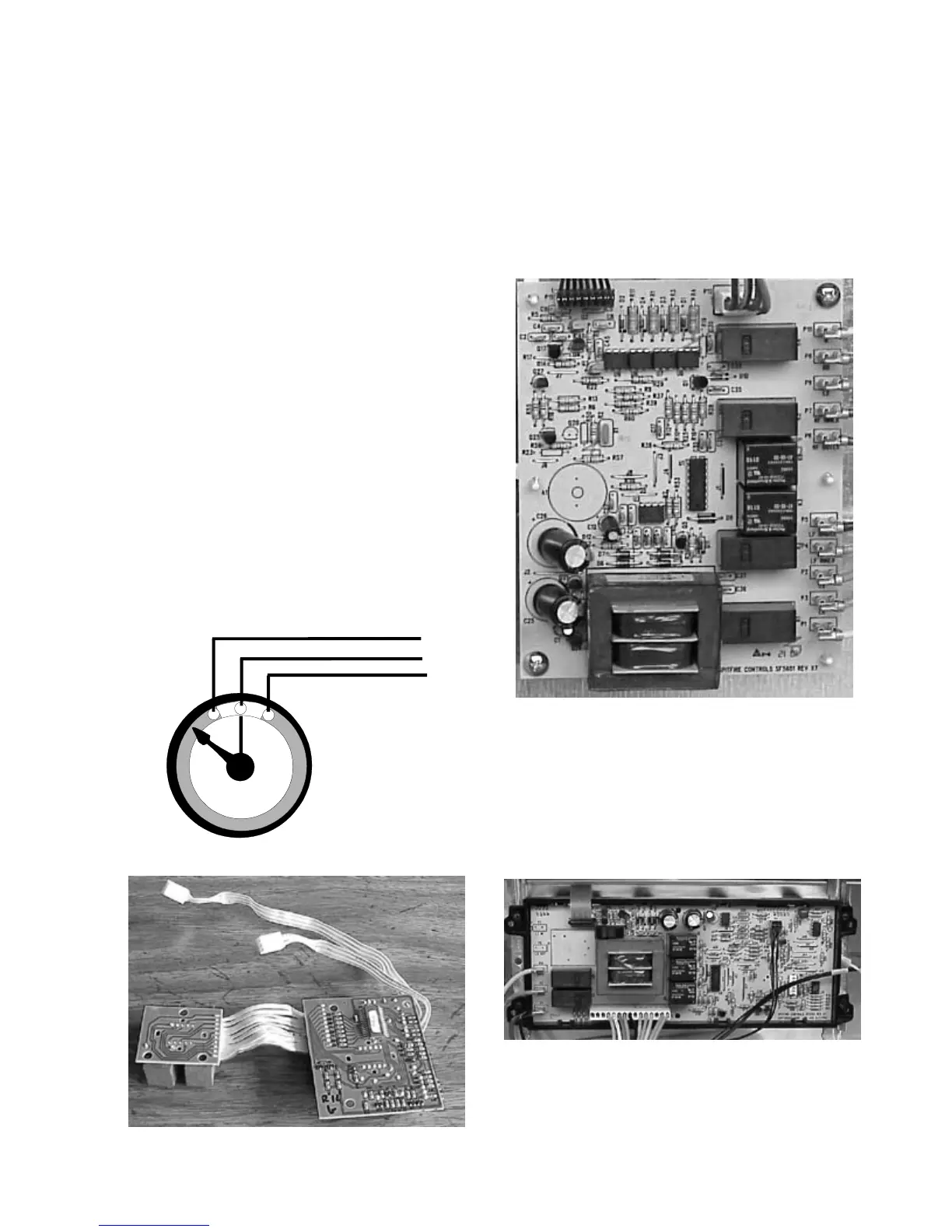
3. One mother board - main circuit board that has a
transformer to provide low voltage for the system, a
microprocessor that controls and communicates with
the other components of the system, and relays that
control line to line voltage to the top elements.
Mother Board
4. A section of the electronic oven control (EOC) -
communicates with the mother board to allow a lockout
feature on the EOC that prevents the oven or top elements
from operating when activated. It also prevents the top
elements from operating during a self clean cycle.
Electronic Oven Control
5. Top elements - three types are used; a single element,
a dual element, and a bridge element.
Top Element Electronic Control System:
Some electric range models are equipped with electronic
top element controls, these controls are more accurate
and allow for a lower simmer temperature than the
conventional infinite switches.
CAUTION: ON MODELS WITH ELECTRONIC TOP
ELEMENT CONTROLS, LINE 1 IS CONNECTED TO
THE TOP ELEMENTS WHENEVER ELECTRICAL
POWER IS APPLIED TO THE RANGE.
Components of the system:
The top element electronic control system (engineering
named ESEC 5) is made up of five components;
Potentiometers, User Interface Boards, Mother Board,
Electronic Oven Control, and Top Elements.
1. Four potentiometers (variable resistors) - one for each
top element, that the user changes the resistance of
when they turn the knob. Because of the different types
of elements two different potentiometers are used. A
potentiometer with a resistance of 20,000 Ohms is used
with the single element, and a potentiometer with a
resistance of 10,000 Ohms is used with the dual and
bridge elements. The potentiometers are identified by
the color of their base. The 20,000 Ohm potentiometer
has a gray base, the 10,000 potentiometer has a black
base.
2. Two user interface boards (UIB) - one for each side of
User Interface Board
Potentiometer
 Loading...