10
2
6
1
4
3
7
9
8
5
10
2
3
4
5
6
7
7
7
9
8
15
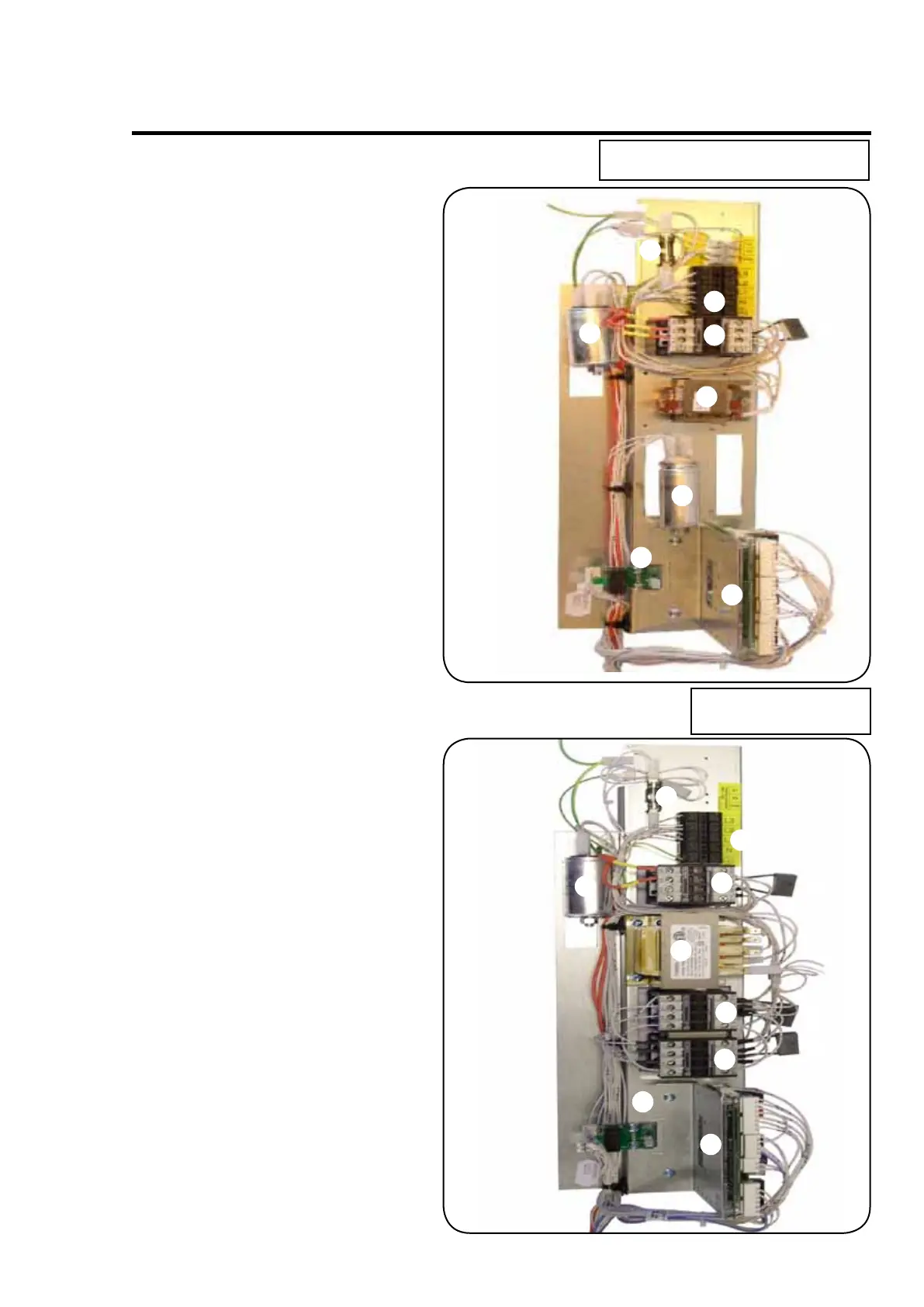
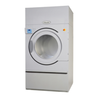
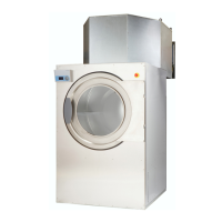
Description of principal components
Service
manual
1. B1 Connection terminal
2. TR1 Transformer
3. K4 Contactor, heat
4. K1 Contactor (drum right)
5. K2 Contactor (drum left)
6. Cn X/Y capacitor
7. RC RC unit
8. PCB1 Selecta II
9. PCB5 Relay for M3
10. F10 Fuse T0.5 A
200-240V 3 AC, 230-240V 1 AC
400-415V 3 AC+N
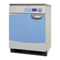
1. B1 Connection terminal
2. Ext Connection max
1,25A 230V AC
3. TR1 Transformer
4. K4 Contactor, heat
5. Cn X/Y Capacitor
6. RC RC unit
7. C Motor operating
c apacitor
8. PCB1 Selecta II
9. PCB5 Relay for M3
10. F10 Fuse T2.5 A
400-440V + 3 AC
without N
1