Do you have a question about the Electrolux T4130 and is the answer not in the manual?
Critical service information regarding measurements and equipment handling.
Guidelines to protect sensitive electronic components from static discharge damage.
Default operational parameters set at the factory for time, temperature, and reversing.
Location and reprogramming procedure for the main control board module.
Definitions of abbreviations and technical terms used throughout the manual.
Information on how to read and identify the installed software version.
How to locate and interpret the hardware version label on the PCB.
Procedure for reading the parameter version via the control menu.
References P1-P23 connectors used in error analysis and wiring diagrams.
Cautionary note regarding high voltage areas on the printed circuit board.
Lists the purpose and function of each connection port P1 through P23 on the PCB.
Visual representation of the machine's software menu hierarchy and navigation flow.
Steps to activate the service mode using the service switch on the CPU board.
Explains how to navigate through submenus like SERVICE, CONFIG 1, and CONFIG 2.
Describes the confirmation process required to save changes made in service menus.
How to engage the Selecta mode on the Compass display for specific operations.
Procedure to enter Boot mode for downloading new software to the CPU board.
How to select and enter submenus within the main service menu.
Lists functions like Activate Outputs, Show Inputs, Article Number, etc. available in service mode.
How to select and activate specific machine outputs like HEAT, DIRECTION, FAN, and DRUM.
Lists sensor signals (inputs) that can be monitored, such as DOOR CLOSED, VACUUM, and GAS INPUT.
How to access and view the article numbers and software/parameter versions.
Displays the status of communication according to the current protocol.
Shows the status of the Input/Output board for system diagnostics.
Instructions on how to run a display test to check segment integrity.
Access to parameters affecting the user interface like button clicks and display timeouts.
Options to show or hide coin and hour counters on the display.
Settings for language selection and special control functions.
Settings related to input/output board addresses and activation.
Adjusting audio feedback for button presses and standby display values.
Configuring display timeouts, end buzzer, and temperature display options.
General method for adjusting numerical parameter values using the control knob.
Setting to display the coin counter on the machine's screen.
Setting to display the hour counter on the machine's screen.
Setting the default language for the machine interface.
Defining the inactivity period before the language reverts to default.
Choosing between Celsius (°C) or Fahrenheit (°F) for temperature display.
Enabling or disabling the I/O board functionality.
Information on specific I/O board numbers and their assignments.
Procedure to enter the password to access the protected CONFIG 2 menu.
Lists submenus within CONFIG 2, including CONFIG PCB, TEMPERATURE, ROTATION, etc.
Settings for drum reversing function and type of heating system.
Configuration options for payment methods, control panel, and program types.
Setting the inlet air temperature range for the drying process.
Configuring hysteresis for outlet temperature and autostop conditions.
Setting the duration for clockwise drum rotation when reversing is active.
Configuring pause duration between reversals and the duration of the reversing action.
Enabling or disabling the anticrease feature to reduce fabric creasing.
Setting the number of available programs and maximum times for time/automatic programs.
Setting the delayed start time for the dryer after it has been stopped.
Procedure to reset the total accumulated service hours of the dryer.
Procedure to reset the trip run hours counter.
Setting the dryer's network address and communication speed.
Configuring network timeout settings and specifying the dryer model.
Reserved for manufacturer use only; no user-configurable options are described.
Explains the dryer's automatic diagnostic system and error message display.
General guidance on how to follow diagnostic procedures for error codes.
Detailed list of error codes E01 to E24 with their descriptions and potential causes.
Items to check concerning airflow for overheating error codes.
Items to check related to the gas connection for potential overheating issues.
Details the error caused by a short-circuited inlet air thermistor or harness.
Step-by-step troubleshooting for E03, including resistance checks and PCB replacement.
Procedure to measure voltage between GND and T2 as an alternative diagnostic step.
Details the error caused by a short-circuited outlet air thermistor or harness.
Step-by-step troubleshooting for E04, including resistance checks and PCB replacement.
Procedure to measure voltage between GND and T1 as an alternative diagnostic step.
Indicates thermal protection switch open in fan motor or its harness.
Troubleshooting steps for E05, including motor checks and PCB replacement.
Indicates thermal protection switch open in drum motor or its harness.
Troubleshooting steps for E06, including motor checks and PCB replacement.
Indicates error code E07 is currently not in use.
Error due to open high limit or overheating thermostat or its harness.
Troubleshooting steps for E08, including fuse check, continuity test, and parameter check.
Indicates error code E09 is currently not in use.
Occurs when parameter setup is inconsistent, requiring reprogramming.
Steps to restore factory settings or re-enter user parameters to resolve E10.
E11 occurs if RMC system does not register dryness within 90 minutes.
Troubleshooting steps for E11, including wiring checks, heating, and overfilling.
Procedure to reset the dryer after resolving an E11 error.
E12 occurs if Auto Stop system does not register dryness within 90 minutes.
Troubleshooting steps for E12, including heating, overfilling, and parameter checks.
Procedure to reset the dryer after resolving an E12 error.
Occurs with payment systems requesting longer drying time than default.
Checks for payment system setup, connection errors, or PCB issues.
Occurs when ignition control fails to detect flame, signaling gas valve closure.
Notes differences in error code display timing between USA/Japan and Europe.
Procedure to reset the dryer after a gas ignition error.
Detailed troubleshooting steps for gas ignition failures, including flame sensor and spark checks.
Triggered if air pressure or vacuum switch does not shut within 12 seconds.
Troubleshooting steps for E15, including underpressure, motor rotation, and PCB checks.
Procedure to reset the dryer after resolving an E15 error.
Occurs if vacuum or air pressure switch is already closed at startup.
Troubleshooting steps for E16, including heat setting, voltage checks, and harness.
Procedure to reset the dryer after resolving an E16 error.
Error displayed when the inlet PT100 sensor is disconnected.
Troubleshooting for E17, involving resistance checks and PCB replacement.
Procedure to measure voltage between GND and T2 for diagnosis.
Procedure to reset the dryer after resolving an E17 error.
Error displayed when the outlet NTC sensor is disconnected.
Troubleshooting for E18, involving resistance checks and PCB replacement.
Procedure to measure voltage between GND and T1 for diagnosis.
Procedure to reset the dryer after resolving an E18 error.
Indicates error code E19 is currently not in use.
Displayed if the dryer is put out of order in the CMIS program.
Refers to a separate manual for detailed analysis of E20 errors.
Occurs when PC does not communicate with dryer in CMIS system.
Troubleshooting steps for E21, involving CMIS start, network connection, and setup.
Occurs when PC does not communicate with dryer in LM10 system.
Troubleshooting steps for E22, involving LM10 start, network connection, and setup.
Indicates error code E23 is currently not in use.
Displayed if pump tries to empty container without level sensor detecting a drop.
Troubleshooting steps for E24, including drain checks, heating type, and relay check.
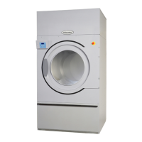
| Model | T4130 |
|---|---|
| Heat Source | Electric |
| Color | White |
| Drying Programs | Cottons, Synthetics, Delicates, Wool |
| Dimensions (H x W x D) | 850 x 600 x 600 mm |
| Noise Level | 65 dB |