24
3.4. Trigger
When triggered the Electrostatic Powder Application Control unit will start applying static electricity to the sprayed powder paint.
The trigger conguration can be done in two different ways.
1. Using the Gun Trigger. (In a manual conguration)
2. If the POWER IN socket on the control unit is fed from the number three (3) meaning the terminal control unit’s POWER IN
socket number 3 feed, starting up a precongured equipment will be done via pressing the B1 interface button. If the
control unit is active, this led will be lit. If the number three (3) cable socket is fed the powder paint will be blown it
will be statically loaded.
Warning: The 1.0 coded POWER IN socket’s inner connections and the fuse connections at the other end should be done by the
ELECTRON technicians at the installation. Electron does not accept any responsibility for the possible damage if the equipment is altered or used
before installation.
C1 Parameter B1 Button Status System Operation
0 = Automatic
Enabled
The device is ready to be triggerred. The device will be
triggerred when mains phase voltage is applied to pin #3 of
POWER IN socket.
Disabled
The device is disabled to be triggerred. The device will not
be triggerred even if phase voltage is applied to pin #3 of
POWER IN socket.
1 = Manual (w/or w/out hopper)
Enabled
AUX socket is powered continously.
Disabled
AUX socket is disabled.
2 = Manual (Multicolor/Stirrer)
Enabled
AUX socket is powered depending on triggering. AUX is
kept powered during triggering and turns off after the time
dened in parameter C3 following trigger release.
Disabled
AUX socket is disabled.
B1 Button Function Table
Pressing the gun trigger on the manual gun or using the electrical trigger on the automatic gun, if the high voltage and the air/powder ratio
adjustments are done, the guns will be spraying statically loaded powder paint. The user can observe this occurrence from the green lit led
(D-T marked) in front of the control unit.
3.5.
Fluidization
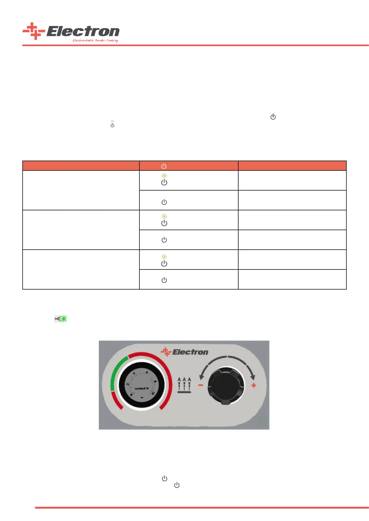
A “Fluidization Control Panel” is placed on the mobile device carrier for the operator to easily adjust the uidization pressure
for H type devices with hopper or M type devices with box uidizied suction tubes. Turning the regulator knob counter-clockwise
will degrease or clockwise will increase the applied pressure to the uidization nozzle in the system. The green and red areas are
signed to indicate the approximate operating pressure values for the uidization air. The uidization will start in parallel with
the vibration motor when the device is triggered if the button is enabled for “M” type multicolor sets. The uidization will be
activated all the time when the device is energized and the button is enabled for “H” type hopper sets.
Fluizidation Control Panel