1.1 System Description:
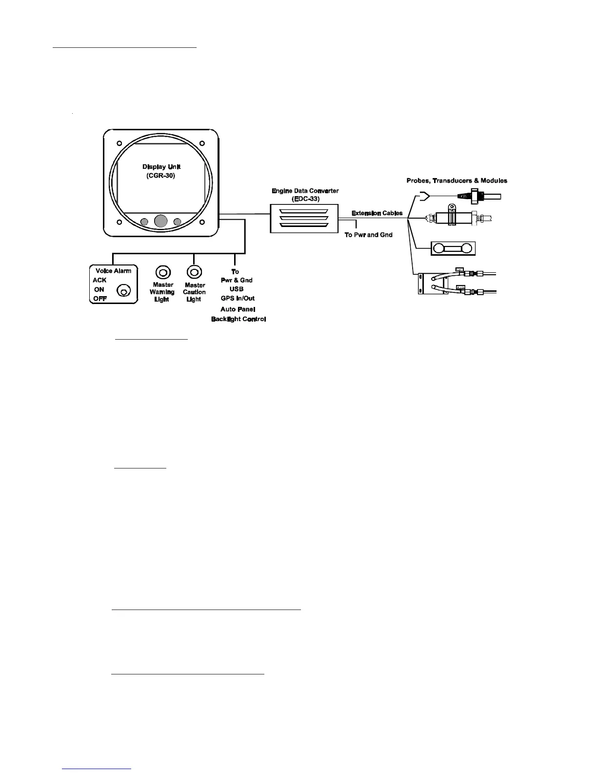
The CGR-30C Glass Panel Engine Monitor installation consists of four major components: CGR Display,
Engine Data Converter (EDC-33P), Probes, Transducers & Modules, and the Wiring and Extension
Cables.
4
1.1.1 1.1.1
1.1.1 1.1.1
1.1.1
CGR Display:CGR Display:
CGR Display:CGR Display:
CGR Display:
The CGR-30C (CGR) display measures 3.25" wide by 3.25" high by 4.36" deep and is designed to
be mounted from behind the aircraft instrument panel into a standard 3 1/8" (3.125") hole.
The 25-pin D-sub connector on the back of the CGR display is used to interface the CGR to the
EDC-33P, Power & Ground, Master Warning and Caution Lights and Audio Panel (experimental
only).
1.1.2 1.1.2
1.1.2 1.1.2
1.1.2
EDC-33P:EDC-33P:
EDC-33P:EDC-33P:
EDC-33P:
The EDC-33P (Engine Data Converter, "EDC") converts all of the engine and aircraft system
signals into serial data. This data is transmitted to the CGR display via one wire 5V-Serial Bus. Up
to two EDC’s can be connected to the CGR display. The EDC measures 4.5" long by 3.5" wide by
2.2" high and is to be mounted on cockpit side of the firewall or in an equipment bay. The EDC
reduces the wire bundle to the instrument panel by over 100 wires. There are three 37-pin D-sub
connectors that interface the EDC to the various probes, transducers and modules. A single EDC
may be used to drive multiple CGR display units.
1.1.3 1.1.3
1.1.3 1.1.3
1.1.3
Probes, Transducers and Modules:Probes, Transducers and Modules:
Probes, Transducers and Modules:Probes, Transducers and Modules:
Probes, Transducers and Modules:
The various probes, transducers and modules are mounted in the aircraft at appropriate locations.
1.1.4 1.1.4
1.1.4 1.1.4
1.1.4
Wiring & Extension Cables:Wiring & Extension Cables:
Wiring & Extension Cables:Wiring & Extension Cables:
Wiring & Extension Cables:
The extension cables and wiring provide the connections from the probes, modules or direct connec-
tions to the EDC inputs. Once the Wiring and Extension Cables are installed into the aircraft they