26
1) If the two instruments a mounted side-by-side, install the Mounting Plates horizontally,
side-by-side with the left Plate annunciating the left instrument or mount the Plates verti-
cally, top-to-bottom with the top Plate annunciating the left instrument.
2) If the two instruments a mounted top-to-bottom, install the Mounting Plates vertically,
top-to-bottom with the top Plate
annunciating the top instrument or
mount the Plates horizontally,
side-by-side with the left Plate
annunciating the top instrument.
C. The CGR-30C remote lights and mount-
ing plate must be installed in a location
where the placard will be readable in all
lighting conditions. Installing the annunciators near an exiting lighting source or installing a post
light are acceptable methods of compliance, other methods may also be acceptable.
D. Mark the aircraft instrument panel (using the mounting plate as a guide) and drill a 5/16" hole for
each light. Install the Red Warning Light, Yellow Caution Light and Mounting Plate in the
instrument panel.
Note: If the CGR Master Warning and Caution Outputs are connected to other lights or de-
vices, the current must be limited to 0.1 amps. The outputs pull to ground when active.
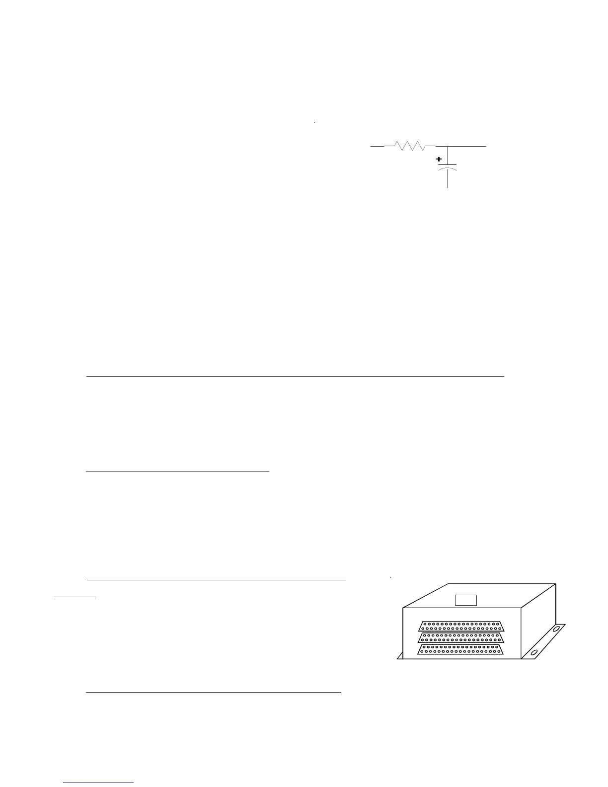
2.16 Install the Interface Circuit for a PWM Backlight System (Optional):
If a PWM backlight system will be used to control the CGR-30 screen intensity, place the following
circuit in series with the CGR-30 backlight wire.
2.17 Install the USB-6A (Optional):
The CGR-30 provides a USB port to upload configuratoin data and to download flight data. The USB-6A
allows the USB port to be mounted on the aircraft instrument panel. Otherwise, the port will only be
available via a USB connector (dongle) located under the instrument panel. To install the USB-6A, follow-
ing the instructions provided with the unit.
2.18 Install the FM-SC or AC-1 Converter (Op-
tional):
The FAA PMA'd FM-SC and AC-1 are used to convert engine data
from a FADEC unit to the CGR-30. To install the converter
following the instructions provide with the approprate unit.
2.19 Install any Additional Modules (Optional):
Top
PWM Signal
Gnd
To CGR-30 Backlight
100uF, 35V
4.99K, 1%, 1/4W