System, connect the Ring Terminal Isolators (found in the RPM Isolator packet) to the P-leads on the back
of the Mag Switch. Connect the EDC RPM Ch 1 and Ch 2 wires (White/Brown and White/Orange) to the
RPM Isolators.
If the EDC RPM Ch 1 and Ch 2 Inputs are to be connected to an electronic ignition system, connect the
EDC RPM Ch 1 and Ch 2 wires (White/Brown and White/Orange) directly to the electronic ignition
system RPM output (do not use any isolators). Without isolators the EDC RPM Ch 1 and Ch 2 Inputs
have a 3-volt trigger level and will accommodate 0 to 5-volt, 0 to 12-volt or 0 to 24-volt signals. If only
one RPM signal is available, connect only one of the EDC RPM channels.
WARANING: Connecting an EDC RPM input directly to a magneto without an Isolator will damage
the EDC. Be sure there is an Isolator in each RPM input lead connected to a magneto, ignition coil or
CDI ignition.
3.12 Set up the EDC for a 4 or 6-Cylinder Engine:
If the EDC-33P is to be used on a 6-cylinder engine, strap Pin 28 to Pin 27 on the EDC Bottom Connector.
Leave these pins open for a 4-cylinder engine. This strap may already be installed or can be found in the
kit.
34
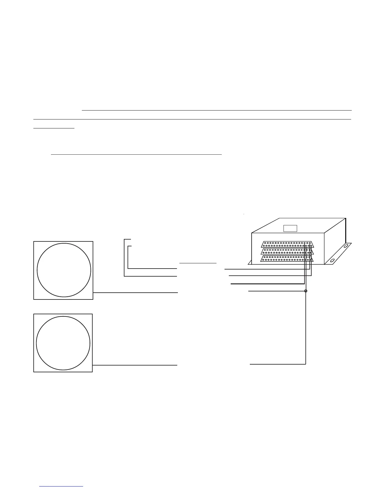
Top
5V-Serial Output (pin 6)
Pin 37, Red Wire
Pin 19 Black Wire
Pin 18, White/Green Wire
CGR-30C
To Aircraft Ground
To the CGR/EDC 5-amp Circuit Breaker
EDC-33P
Top Connector
5V-Serial Output (pin 6)
CGR-30P
Pin 18, White/Green Wire
Note: The CGR-30P may
already be installed in the
aircraft.
Splice
Note: The EDC-33P may
already be installed in the
aircraft.